Wednesday, January 28, 2015
Monday, January 12, 2015
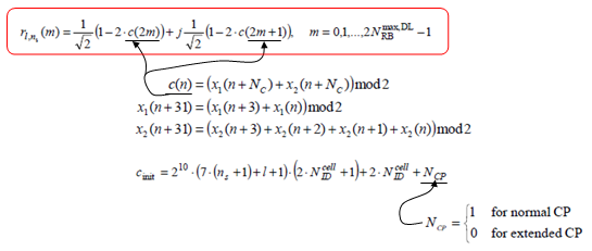
Reference Signal positioning
Signal
generation is done by the following procedure. You would notice that
Cell ID is a key parameter for the sequence and you would guess the
sequence will be unique for each Cell ID.
Another
think you would notice here would be that downlink reference signal is a
kind of Gold sequence whereas most of UL reference signal and DL
Synchronization signal is based on Zadoff Chu sequence.
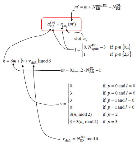
Once
you have generated the sequence, next step is to allocate each data
point of the sequence to a specified resource elements. That is done by
the following process. The resulting location of the process is as shown
in Reference Signal section of Downlink Frame Structure
page.
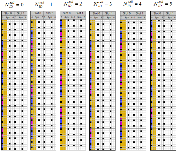
Note 1 : The DL Reference Signal (Cell Specific Reference Signal) is mainly determined by Physical Cell ID.
Note
2 : The resource element locations for DL reference signal gets
different according to Physical Cell ID, but there is possibility that
the reference signal location with two different physical cell ID can be
same if (PCI1 mod 6) == (PCI2 mod 6). (PCI stands for Physical Cell
ID). It means that you should be careful when you allocate the physical
cell ID for multiple cells
in a specific area. Following is some of examples of Reference Signal
Location with different physical cell IDs.
(I created following subframe structure using LTE Resource Grid and edited to fit the topics of this page)
Subscribe to:
Posts (Atom)
The T301 timer is started when the UE sends an RRCConnectionReestablishmentRequestfollowing a radio link failure. If the timer expires before the UE has received an RRCConnectionRestablishmentor an RRCConnectionReestablishmentReject, the UE enters Idle mode.
The T310 timer is started when Physical layer problems are detected whereby the UE receives N310 out-of-sync indicators. The timer is stopped if N311 in-sync indicators are received. If T310 expires, the UE either enters Idle mode or initiates the connection reestablishment procedure, depending on whether security is activated.
The T311 timer is started when the RRC reconnection procedure is started. If the timer expires before the selection of a suitable LTE (or other RAT) cell, the UE enters Idle mode.