|
In
this section, I will go through a typical protocol sequence of LTE
packet call. This will be the backbone structure for all other call
processing.
Following
is the over protocal sequence being exchanged between UE and Network.
Actually understanding all the details of these steps would be the goal
of your whole LTE career.
19) RRC : RRC Connection Release
22) < MO or MT call > : In MT call, Paging should be sent.
32) RRC : RRC Connection Release
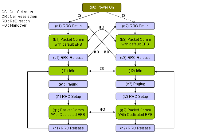
Following
diagram shows a possible state machine that a UE would go through. The
state transition in this post will be about (s0)->(a)-> (b1) ->
(c1) -> (d1) -> (e1) -> (f1) -> (g1) -> (h1). Most of
other transition will be described in "Handover" page.
Note
for Step 23)~32) : Intial Registration and Default EPS Bearer Setup
procedure would be common to almost all LTE network. Of course, there
would be a small variations but overall concept would be almost same.
But the procedure after <Idle> (Step 23~32) would be quite
different among Network Operators. Following would be two major
variations.
- Setup
RRC Connection, RRC Connection Reconfiguration without creating any
dedicated EPS Bearer.(In this case, UE uses the existing Default EPS
bearer for traffic).
- Setup
RRC Connection, RRC Connection Reconfiguration with a dedicated EPS
Bearer.(In this case, Ue uses the existing Default EPS bearer or
Dedicated EPS Bearer depending on situation).
The example test sequence in this case shows the second case,
Depending
on which level you are working on in UE development/Test procedure, the
amount of knowledge you need to know would be different. But I think
there are a couple of big pictures that may help almost anybody working
in full protocol stack.
First
big picture I would like to introduce is the channel mapping as shown
below. Just try to pick any RRC messages and try to follow the arrow for
the message. If you read those pages about MAC and RLC, it will remind
you of a lot of detailed information.
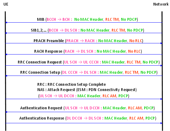
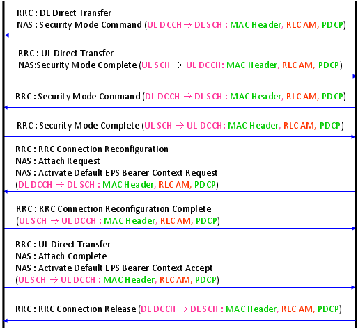
<< Overall Sequence and Layer Mapping >>
Following
is a sequence diagram showing not only the message but also basic
configurations of each layer. More detailed description of each layer in
the context of full protocol stack will be explained in "Full Stack" section.
Just
read through this sequence whenever you have time until you can
duplicate the sequence without looking into this again. This can be a
good framework for your study and good guide for troubleshooting.
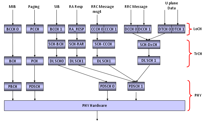
<< Downlink Channel Map >>
The
diagram you saw above a kind of message flow(event diagram) in time
sequence. The diagram shown below is not a time based, but it shows the
channel mapping (or data flow across the full protocol stack). Pick one
of the message from the diagram shown above and try to find right route
for this digram and see how much details you can add.
For example, if you picked the message "RRC Connection Setup", the start point would be "RRC Message msg4".
Following
is a tabular presentation of DL Channel Map. (LCID and TrCH Number
would be different depending on the network or Network Simulator)
|
RB
|
Lo CH
|
PDCP
|
RLC
|
Lo CH
|
LCID
|
MAC Hdr
|
HARQ
|
RNTI
|
Tr CH
|
|
|
PCCH
|
|
TM
|
PCCH
|
N/A
|
NONE
|
NONE
|
NONE
|
PCH
|
| |
BCCH 0
|
|
TM
|
BCCH 0
|
N/A
|
NONE
|
NONE
|
NONE
|
BCH 0
|
| |
BCCH 1
|
|
TM
|
BCCH 1
|
N/A
|
NONE
|
Broadcast
|
SI RNTI
|
DL SCH 0
|
| |
RA_RES
|
|
TM
|
RA_RES
|
N/A
|
NONE
|
NONE
|
RA RNTI
|
DL SCH 1
|
|
SRB0
|
DL CCCH
|
USED
|
TM
|
DL CCCH
|
0
|
NONE
|
NORMAL
|
T-CRNTI
|
DL SCH 1
|
|
SRB1
|
DL DCCH 0
|
USED
|
AM
|
DL DCCH 0
|
1
|
NORMAL
|
NORMAL
|
CRNTI
|
DL SCH 1
|
|
SRB2
|
DL DCCH 1
|
USED
|
AM
|
DL DCCH 0
|
2
|
NORMAL
|
NORMAL
|
CRNTI
|
DL SCH 1
|
|
DRB 0
|
DL DTCH0
|
USED
|
UM/AM
|
DL DTCH0
|
3
|
NORMAL
|
NORMAL
|
CRNTI
|
DL SCH 1
|
|
DRB 1
|
DL DTCH1
|
USED
|
UM/AM
|
DL DTCH1
|
4
|
NORMAL
|
NORMAL
|
CRNTI
|
DL SCH 1
|
|
DRB 2
|
DL DTCH2
|
USED
|
UM/AM
|
DL DTCH2
|
5
|
NORMAL
|
NORMAL
|
CRNTI
|
DL SCH 1
|
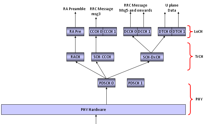
<< Uplink Channel Map >>
Following
is a tabular presentation of DL Channel Map. (LCID and TrCH Number
would be different depending on the network or Network Simulator)
|
RB
|
Lo CH
|
PDCP
|
RLC
|
Lo CH
|
LCID
|
MAC Hdr
|
HARQ
|
RNTI
|
Tr CH
|
| |
RA_PRE
|
|
TM
|
RA_PRE
|
N/A
|
NONE
|
NONE
|
NONE
|
UL SCH 0
|
|
SRB0
|
UL CCCH
|
USED
|
TM
|
UL CCCH
|
0
|
NONE
|
NORMAL
|
T-CRNTI
|
UL SCH 0
|
|
SRB1
|
UL DCCH 0
|
USED
|
AM
|
UL DCCH 0
|
1
|
NORMAL
|
NORMAL
|
CRNTI
|
UL SCH 0
|
|
SRB2
|
UL DCCH 1
|
USED
|
AM
|
UL DCCH 0
|
2
|
NORMAL
|
NORMAL
|
CRNTI
|
UL SCH 0
|
|
DRB 0
|
UL DTCH0
|
USED
|
UM/AM
|
UL DTCH0
|
3
|
NORMAL
|
NORMAL
|
CRNTI
|
UL SCH 0
|
|
DRB 1
|
UL DTCH1
|
USED
|
UM/AM
|
UL DTCH1
|
4
|
NORMAL
|
NORMAL
|
CRNTI
|
UL SCH 0
|
|
DRB 2
|
UL DTCH2
|
USED
|
UM/AM
|
UL DTCH2
|
5
|
NORMAL
|
NORMAL
|
CRNTI
|
UL SCH 0
|
This
is only an example case and Mapping (especiall LoCH No) can vary
depending on situations. The point is that it will be really helpful for
your troubleshooting or test case creation if you create this kind of
table for your case.
|
Message
|
RB
|
Lo CH
|
LoCH No
|
LCID
|
|
MIB
|
-
|
BCCH
|
0
|
-
|
|
SIB 1
|
-
|
BCCH
|
1
|
-
|
|
SIB 2
|
-
|
BCCH
|
1
|
-
|
|
RRC : PRACH Preamble
|
-
|
-
|
-
|
-
|
|
RRC : RACH Response
|
-
|
-
|
-
|
-
|
|
RRC : RRC Connection Request
|
SRB0
|
UL CCCH
|
0
|
0
|
|
RRC : RRC Connection Setup
|
SRB0
|
DL CCCH
|
0
|
0
|
|
RRC : RRC Connection Setup
Complete + NAS : Attach Request + ESM : PDN Connectivity Request
|
SRB1
|
UL DCCH
|
0
|
1
|
|
RRC : DL Information Transfer
+ NAS : Authentication Request
|
SRB1
|
DL DCCH
|
0
|
1
|
|
RRC : UL Information Transfer
+ NAS : Authentication Response
|
SRB1
|
UL DCCH
|
0
|
1
|
|
RRC : DL Information Transfer
+ NAS : Security Mode Command
|
SRB1
|
DL DCCH
|
0
|
1
|
|
RRC : UL Information Transfer
+ NAS : Security Mode Complete
|
SRB1
|
UL DCCH
|
0
|
1
|
|
RRC : Security Mode Command
|
SRB1
|
DL DCCH
|
0
|
1
|
|
RRC : Security Mode Complete
|
SRB1
|
UL DCCH
|
0
|
1
|
|
RRC : RRC Connection
Reconfiguration
|
SRB1
|
DL DCCH
|
0
|
1
|
|
RRC
: RRC Connection Reconfiguration Complete
|
SRB1
|
UL DCCH
|
0
|
1
|
|
RRC
: UL InformationTransfer + NAS : Attach Complete + NAS : Activate Default EPS
Bearer
|
SRB2
|
UL DCCH
|
1
|
2
|
|
RRC : UL Information Transfer
+ ESM : PDN Connectivity Request
|
SRB2
|
UL DCCH
|
1
|
2
|
Note : Refer to TS 36.331 - 9.1.1 Logical channel configurations
Config 1) Activate Cell Physicall Layer
1) MIB
Config 2) Activate PHY, MAC, RLC for SIB Transmission (BCCH-DL DSCH)
2) SIB 1
3) SIB 2
Config 3) Configure PHY, MAC for PRACH Reception and RACH Response Transmission
4) RRC : PRACH Preamble
5) RRC : RACH Response
Config 3) Configure PHY, MAC, RLC for Msg3 (RRC Connection Request) Reception (UL-CCCH)
6) RRC : RRC Connection Request
Config 4) Configure MAC, RLC, PDCH for DL DCCH, UL DCCH
7) RRC : RRC Connection Setup
8) RRC : RRC Connection Setup Complete + NAS : Attach Request + ESM : PDN Connectivity Request
9) RRC : DL Information Transfer + NAS : Authentication Request
10) RRC : UL Information Transfer + NAS : Authentication Response
11) RRC : DL Information Transfer + NAS : Security Mode Command
12) RRC : UL Information Transfer + NAS : Security Mode Complete
Config 5) Configure PDCP for Integrity, Ciphering (We may disable Integiry/Ciphering for some test environment)
13) RRC : Security Mode Command
14) RRC : Security Mode Complete
15) RRC : RRC Connection Reconfiguration + NAS : Attach Accept + NAS : Activate Default EPS Bearer Context Req
Config 6) Configure MAC, RLC, PDCP for DL/UL DTCH+DCCH
16) RRC : RRC Connection Reconfiguration Complete + NAS : Attach Complete + NAS : Activate Default EPS Bearer Context Accept
17) RRC : RRC Connection Release
Config 7) Deactivate all the channels related to DCCH, DTCH
Config 8) Activate channels for PCCH
< MO or MT call > : In MT call, Paging should be sent.
Config 9) Configure PHY, MAC for PRACH Reception and RACH Response Transmission
18) RRC : PRACH Preamble
19) RRC : RACH Response
Config 10) Configure PHY, MAC, RLC for Msg3 (RRC Connection Request) Reception (UL-CCCH)
20) RRC : RRC Connection Request
Config 11) Configure MAC, RLC, PDCH for DL DCCH, UL DCCH
21) RRC : RRC Connection Setup
22) RRC : RRC Connection Setup Complete + NAS : Service Request
23) RRC : Security Mode Command
24) RRC : Security Mode Complete
25) RRC : RRC Connection Reconfiguration + NAS : Activate Dedicated EPS Bearer Context Request
Config 12) Configure MAC, RLC, PDCP for DL/UL DTCH+DCCH
26) RRC : RRC Connection Reconfiguration Complete + NAS : Activate Dedicated EPS Bearer Context Accept
27) RRC : RRC Connection Release
Now
the next step is to describe each of the steps in as much detail as
possible. The more in detail you can describe, the easier the
development, testing, troubleshooting will be. There are many steps I
couldn't describe here because the most of steps not described here
would be related to company confidentials (Of course, you can say "Every
details are in 3GPP specification".
Yes, that's true, but 3GPP says only about "What to do", it doesn't say
much about "How to do". In real implementation, this "How to do" part is
as important as "What to do") You can take this as a minimum of
possible-detailed description. Going through this table, think about how
much additional comments you think you can put in 'Memo' column. (If
you want to see what's really happening in real network, see the live air example in Full Stack page)
|
Step
|
Direction
|
Message
|
Memo
|
| 1 |
UE <--- SS |
MIB |
|
| 2 |
UE <--- SS |
SIB1 |
|
| 3 |
UE <--- SS |
SIB2,3 and others |
|
| 4 |
UE ---> SS |
PRACH
|
|
| 5 |
UE <--- SS |
RACH Response
|
|
| 6 |
UE ---> SS |
RRC Connection Request
|
|
| |
< UE >
|
UE MAC start mac-ContentionResolutionTimer
|
3GPP 36.321 5.1.5
CR Timer value is set in SIB2
|
| 7 |
UE <--- SS |
ACK (PHICH) |
|
| 8 |
UE <--- SS |
Contention Resolution |
SS must send CR before CRtimer get expired |
| |
< UE > |
UE MAC stop mac-ContentionResolutionTimer
|
|
| 9 |
UE <--- SS |
RRC Connection Setup
|
|
| 10 |
UE ---> SS |
ACK (PUCCH) |
|
| 11 |
UE ---> SS |
Scheduling Request(PUCCH) |
|
| 12 |
UE <--- SS |
UL Grant (DCI 0, PDCCH) |
|
| 13 |
UE ---> SS |
RRC Connection Setup Complete
+ Attach Requeset
+ (PDN Conn Request)
|
|
| 14 |
UE <--- SS |
ACK(PHICH) |
|
| 15 |
UE <--- SS |
RLC ACK |
|
| 16 |
UE <--- SS |
Authentication Request
|
|
| 17 |
UE ---> SS |
ACK (PUCCH) |
|
| 18 |
UE ---> SS |
Scheduling Request(PUCCH) |
|
| 19 |
UE <--- SS |
UL Grant (DCI 0, PDCCH) |
|
| 20 |
UE ---> SS |
RLC ACK |
|
| 21 |
UE ---> SS |
Scheduling Request(PUCCH) |
|
| 22 |
UE ---> SS |
UL Grant (DCI 0, PDCCH) |
|
| 23 |
UE ---> SS |
Authentication Response
|
|
| 24 |
UE <--- SS |
ACK(PHICH) |
|
| 25 |
UE <--- SS |
RLC ACK |
|
| 26 |
UE <--- SS |
NAS Security Mode Command
|
|
| 27 |
UE ---> SS |
ACK (PUCCH) |
|
| 28 |
UE ---> SS |
Scheduling Request(PUCCH) |
|
| 29 |
UE <--- SS |
UL Grant (DCI 0, PDCCH) |
|
| 30 |
UE ---> SS |
RLC ACK |
|
| 31 |
UE ---> SS |
Scheduling Request(PUCCH) |
|
| 32 |
UE <--- SS |
UL Grant (DCI 0, PDCCH) |
|
| 33 |
UE ---> SS |
NAS Security Mode Complete
|
|
| 34 |
UE <--- SS |
ACK(PHICH) |
|
| 35 |
UE <--- SS |
RLC ACK |
|
| 36 |
UE <--- SS |
RRC Security Mode Command
|
|
| 37 |
UE ---> SS |
ACK (PUCCH) |
|
| 38 |
UE ---> SS |
Scheduling Request(PUCCH) |
|
| 39 |
UE <--- SS |
UL Grant (DCI 0, PDCCH) |
|
| 40 |
UE ---> SS |
RLC ACK |
|
| 41 |
UE ---> SS |
Scheduling Request(PUCCH) |
|
| 42 |
UE <--- SS |
UL Grant (DCI 0, PDCCH) |
|
| 43 |
UE ---> SS |
RRC Security Mode Complete
|
|
| 44 |
UE ---> SS |
ACK (PHICH) |
|
| 45 |
UE ---> SS |
RLC ACK |
|
| 46 |
|
< Many other message can be added here depending on NW > |
|
|
47
|
UE <--- SS |
RRC Connection Reconfiguration
+ Attach Accept
+ Activate Default EPS Bearer Context Request
|
|
| 48 |
UE ---> SS |
ACK (PUCCH) |
|
| 49 |
UE ---> SS |
Scheduling Request(PUCCH) |
|
| 50 |
UE <--- SS |
UL Grant (DCI 0, PDCCH) |
|
| 51 |
UE ---> SS |
RLC ACK |
|
| 52 |
UE ---> SS |
RRC Connection Reconfiguration
+ Attach Complete
+ Activate Default EPS Bearer Context Accept
|
|
| 53 |
UE <--- SS |
ACK (PHICH) |
|
| 54 |
UE <--- SS |
RLC ACK |
|
| 55 |
|
< IP Data Traffic if needed > |
|
| 58 |
UE <--- SS |
RRC Connection Release |
|
| 59 |
UE |
< Now UE should be in IDLE mode > |
|
| 60 |
UE |
Decode MIB |
|
| 61 |
UE |
Decode SIB1 |
|
| 63 |
UE |
Decode or Doesn't Decode Other SIBs based on SystemInfoValueTag on SIB1 |
|
| 64 |
UE <--- SS |
Paging |
|
| 65 |
UE ---> SS |
PRACH
|
|
| 66 |
UE <--- SS |
RACH Response
|
|
| 67 |
UE ---> SS |
RRC Connection Request
|
|
| 68 |
UE <--- SS |
ACK (PHICH) |
|
| 69 |
UE <--- SS |
Contention Resolution |
|
| 70 |
UE <--- SS |
RRC Connection Setup
|
|
| 71 |
UE ---> SS |
ACK (PUCCH) |
|
| 72 |
UE ---> SS |
Scheduling Request(PUCCH) |
|
| 73 |
UE <--- SS |
UL Grant (DCI 0, PDCCH) |
|
| 74 |
UE ---> SS |
RRC Connection Setup Complete
+ Service Requeset
|
|
| 75 |
UE <--- SS |
ACK(PHICH) |
|
| 76 |
UE <--- SS |
RLC ACK |
|
|
77
|
UE <--- SS |
RRC Connection Reconfiguration
+ Activate Dedicated EPS Bearer Context Request
|
|
| 78 |
UE ---> SS |
ACK (PUCCH) |
|
| 79 |
UE ---> SS |
Scheduling Request(PUCCH) |
|
| 80 |
UE <--- SS |
UL Grant (DCI 0, PDCCH) |
|
| 81 |
UE ---> SS |
RLC ACK |
|
| 82 |
UE ---> SS |
RRC Connection Reconfiguration
+ Activate Dedicated EPS Bearer Context Accept
|
|
| 83 |
UE <--- SS |
ACK (PHICH) |
|
| 84 |
UE <--- SS |
RLC ACK |
|
| 85 |
|
< IP Data Traffic if needed > |
|
Even
though overall sequence is pretty similar to WCDMA sequence, there are a
couple of different points comparing to WCDMA sequence.
First
point you have to look at is that in LTE 'RACH Preamble' is sent as a
part of MAC Layer process. As you know RACH process was there in WCDMA,
but in WCDMA it was a part of Physical layer process.
Another
part I notice is that RRC Connection Setup Complete and Attach Request
is carried in a single step. This is only one example. In LTE, many of
NAS Message is piggybacked on RRC Messages. This would make message
decoding/encoding process complicated but it would be efficient to
reduce the number of message exchange between UE and eNodeB.
These
are the differences you can notice just by looking at the message type,
there are more differences you will find when you go into the
information elements of each messages as you will see in following
sections.
Next
thing you will notice would be that there are much less SIBs being
transmitted in LTE comparting to WCDMA. Of course there are more SIBs
not being transmitted in this sequence (LTE has 10 SIBs in total), but
with only these two SIBs it can transmit all the information to let UE
camp on the network. In WCDMA there are a total 18 SIBs and in most case
we used at least SIB1,3,5,7,11 even
in very basic configurations. And some of the WCDMA SIBs like SIB5 and
11 has multipe segments. In LTE, number of SIB is small and none of them
are segmented.
MIB in LTE has very minimal information (This is a big difference from WCDMA MIB) . The only information it carries are
i) BandWidth
ii) PHICH
iii) SystemFrameNumber
Of course the most important information is "BandWidth".
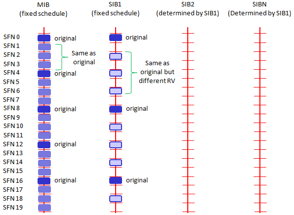
According to 36.331 section 5.2.1.2, the MIB scheduling is as follows :
The
MIB uses a fixed schedule with a periodicity of 40 ms and repetitions
made within 40 ms. The first transmission ofthe MIB is scheduled in
subframe #0 of radio frames for which the SFN mod 4 = 0, and repetitions
are scheduled insubframe #0 of all other radio frames.
SIB 1 in LTE contains the information like the ones in WCDMA MIB & SIB1 & SIB3. The important information on SIB 1 is
i) PLMN
ii) Tracking Area Code
iii) Cell Selection Info
iv) Frequency Band Indicator
v) Scheduling information (periodicity) of other SIBs
You may notice that LTE SIB1 is very similar to WCDMA MIB.
Especially
at initial test case development, you have to be very careful about
item v). If you set this value incorrectly, all the other SIBs will not
be decoded by UE. And as a result, UE would not recognize the cell and
show "No Service" message.
According to 36.331 section 5.2.1.2, the SIB1 scheduling is as follows :
The
SystemInformationBlockType1 uses a fixed schedule with a periodicity of
80 ms and repetitions made within 80 ms.The first transmission of
SystemInformationBlockType1 is scheduled in subframe #5 of radio frames
for which the SFNmod 8 = 0, and repetitions are scheduled in subframe #5
of all other radio frames for which SFN mod 2 = 0.
This
means that even though SIB1 periodicity is 80 ms, different copies
(Redudancy version : RV) of the SIB1 is transmitted every 20ms. Meaning
that at L3 you will see the SIB1 every 80 ms, but at PHY layer you will
see it every 20ms. For the detailed RV assignment for each transmission,
refer to 36.321 section 5.3.1 (the last part of the section)
One example of LTE SIB1 is as follows :
RRC_LTE:BCCH-DL-SCH-Message
BCCH-DL-SCH-Message ::= SEQUENCE
+-message ::= CHOICE [c1]
+-c1 ::= CHOICE [systemInformationBlockType1]
+-systemInformationBlockType1 ::= SEQUENCE [000]
+-cellAccessRelatedInfo ::= SEQUENCE [0]
| +-plmn-IdentityList ::= SEQUENCE OF SIZE(1..6) [1]
| | +-PLMN-IdentityInfo ::= SEQUENCE
| | +-plmn-Identity ::= SEQUENCE [1]
| | | +-mcc ::= SEQUENCE OF SIZE(3) OPTIONAL:Exist
| | | | +-MCC-MNC-Digit ::= INTEGER (0..9) [0]
| | | | +-MCC-MNC-Digit ::= INTEGER (0..9) [0]
| | | | +-MCC-MNC-Digit ::= INTEGER (0..9) [1]
| | | +-mnc ::= SEQUENCE OF SIZE(2..3) [2]
| | | +-MCC-MNC-Digit ::= INTEGER (0..9) [0]
| | | +-MCC-MNC-Digit ::= INTEGER (0..9) [1]
| | +-cellReservedForOperatorUse ::= ENUMERATED [notReserved]
| +-trackingAreaCode ::= BIT STRING SIZE(16) [0000000000000001]
| +-cellIdentity ::= BIT STRING SIZE(28) [0000000000000000000100000000]
| +-cellBarred ::= ENUMERATED [notBarred]
| +-intraFreqReselection ::= ENUMERATED [notAllowed]
| +-csg-Indication ::= BOOLEAN [FALSE]
| +-csg-Identity ::= BIT STRING OPTIONAL:Omit
+-cellSelectionInfo ::= SEQUENCE [0]
| +-q-RxLevMin ::= INTEGER (-70..-22) [-53]
| +-q-RxLevMinOffset ::= INTEGER OPTIONAL:Omit
+-p-Max ::= INTEGER OPTIONAL:Omit
+-freqBandIndicator ::= INTEGER (1..64) [7]
+-schedulingInfoList ::= SEQUENCE OF SIZE(1..maxSI-Message[32]) [2]
| +-SchedulingInfo ::= SEQUENCE
| | +-si-Periodicity ::= ENUMERATED [rf8]
| | +-sib-MappingInfo ::= SEQUENCE OF SIZE(0..maxSIB-1[31]) [0]
| +-SchedulingInfo ::= SEQUENCE
| +-si-Periodicity ::= ENUMERATED [rf8]
| +-sib-MappingInfo ::= SEQUENCE OF SIZE(0..maxSIB-1[31]) [1]
| +-SIB-Type ::= ENUMERATED [sibType3]
+-tdd-Config ::= SEQUENCE OPTIONAL:Omit
+-si-WindowLength ::= ENUMERATED [ms20]
+-systemInfoValueTag ::= INTEGER (0..31) [0]
+-nonCriticalExtension ::= SEQUENCE OPTIONAL:Omit
The important information on SIB2 is
i) RACH Configuration
ii) bcch, pcch, pdsch, pusch, pucch configuration
iii) sounding RS Configuration
iv) UE Timers
I
would say SIB2 is the most important SIB in LTE and you will look into
this SIB most frequently when you are implementing protocol stack and
troubleshooting, since it defines the characteristics of the most
physical channels.
If
you have some issues at registration process especially before 'RRC
Connection Reconfiguration'. The first part you have to check is SIB2
and check if UE properly decoded this and properly configure UE
according to SIB2. Sometimes only one parameter mismatch of SIB2 between
Network and UE can make difference between success and failure of the
whole registration process.
Following is one example of SIB2. I looks to me that LTE SIB2 is similar to WCDMA SIB5 configuring various common channel.
RRC_LTE:BCCH-DL-SCH-Message
BCCH-DL-SCH-Message ::= SEQUENCE
+-message ::= CHOICE [c1]
+-c1 ::= CHOICE [systemInformation]
+-systemInformation ::= SEQUENCE
+-criticalExtensions ::= CHOICE [systemInformation-r8]
+-systemInformation-r8 ::= SEQUENCE [0]
+-sib-TypeAndInfo ::= SEQUENCE OF SIZE(1..maxSIB[32]) [1]
| +- ::= CHOICE [sib2]
| +-sib2 ::= SEQUENCE [00]
| +-ac-BarringInfo ::= SEQUENCE OPTIONAL:Omit
| +-radioResourceConfigCommon ::= SEQUENCE
| | +-rach-Config ::= SEQUENCE
| | | +-preambleInfo ::= SEQUENCE [0]
| | | | +-numberOfRA-Preambles ::= ENUMERATED [n52]
| | | | +-preamblesGroupAConfig ::= SEQUENCE OPTIONAL:Omit
| | | +-powerRampingParameters ::= SEQUENCE
| | | | +-powerRampingStep ::= ENUMERATED [dB2]
| | | | +-preambleInitialReceivedTargetPower ::= ENUMERATED [dBm-104]
| | | +-ra-SupervisionInfo ::= SEQUENCE
| | | | +-preambleTransMax ::= ENUMERATED [n6]
| | | | +-ra-ResponseWindowSize ::= ENUMERATED [sf10]
| | | | +-mac-ContentionResolutionTimer ::= ENUMERATED [sf48]
| | | +-maxHARQ-Msg3Tx ::= INTEGER (1..8) [4]
| | +-bcch-Config ::= SEQUENCE
| | | +-modificationPeriodCoeff ::= ENUMERATED [n4]
| | +-pcch-Config ::= SEQUENCE
| | | +-defaultPagingCycle ::= ENUMERATED [rf128]
| | | +-nB ::= ENUMERATED [oneT]
| | +-prach-Config ::= SEQUENCE
| | | +-rootSequenceIndex ::= INTEGER (0..837) [22]
| | | +-prach-ConfigInfo ::= SEQUENCE
| | | +-prach-ConfigIndex ::= INTEGER (0..63) [3]
| | | +-highSpeedFlag ::= BOOLEAN [FALSE]
| | | +-zeroCorrelationZoneConfig ::= INTEGER (0..15) [5]
| | | +-prach-FreqOffset ::= INTEGER (0..94) [2]
| | +-pdsch-Config ::= SEQUENCE
| | | +-referenceSignalPower ::= INTEGER (-60..50) [18]
| | | +-p-b ::= INTEGER (0..3) [0]
| | +-pusch-Config ::= SEQUENCE
| | | +-pusch-ConfigBasic ::= SEQUENCE
| | | | +-n-SB ::= INTEGER (1..4) [1]
| | | | +-hoppingMode ::= ENUMERATED [interSubFrame]
| | | | +-pusch-HoppingOffset ::= INTEGER (0..98) [4]
| | | | +-enable64QAM ::= BOOLEAN [FALSE]
| | | +-ul-ReferenceSignalsPUSCH ::= SEQUENCE
| | | +-groupHoppingEnabled ::= BOOLEAN [TRUE]
| | | +-groupAssignmentPUSCH ::= INTEGER (0..29) [0]
| | | +-sequenceHoppingEnabled ::= BOOLEAN [FALSE]
| | | +-cyclicShift ::= INTEGER (0..7) [0]
| | +-pucch-Config ::= SEQUENCE
| | | +-deltaPUCCH-Shift ::= ENUMERATED [ds2]
| | | +-nRB-CQI ::= INTEGER (0..98) [2]
| | | +-nCS-AN ::= INTEGER (0..7) [6]
| | | +-n1PUCCH-AN ::= INTEGER (0..2047) [0]
| | +-soundingRS-UL-Config ::= CHOICE [setup]
| | | +-setup ::= SEQUENCE [0]
| | | +-srs-BandwidthConfig ::= ENUMERATED [bw3]
| | | +-srs-SubframeConfig ::= ENUMERATED [sc0]
| | | +-ackNackSRS-SimultaneousTransmission ::= BOOLEAN [TRUE]
| | | +-srs-MaxUpPts ::= ENUMERATED OPTIONAL:Omit
| | +-uplinkPowerControl ::= SEQUENCE
| | | +-p0-NominalPUSCH ::= INTEGER (-126..24) [-85]
| | | +-alpha ::= ENUMERATED [al08]
| | | +-p0-NominalPUCCH ::= INTEGER (-127..-96) [-117]
| | | +-deltaFList-PUCCH ::= SEQUENCE
| | | | +-deltaF-PUCCH-Format1 ::= ENUMERATED [deltaF0]
| | | | +-deltaF-PUCCH-Format1b ::= ENUMERATED [deltaF3]
| | | | +-deltaF-PUCCH-Format2 ::= ENUMERATED [deltaF0]
| | | | +-deltaF-PUCCH-Format2a ::= ENUMERATED [deltaF0]
| | | | +-deltaF-PUCCH-Format2b ::= ENUMERATED [deltaF0]
| | | +-deltaPreambleMsg3 ::= INTEGER (-1..6) [4]
| | +-ul-CyclicPrefixLength ::= ENUMERATED [len1]
| +-ue-TimersAndConstants ::= SEQUENCE
| | +-t300 ::= ENUMERATED [ms1000]
| | +-t301 ::= ENUMERATED [ms1000]
| | +-t310 ::= ENUMERATED [ms1000]
| | +-n310 ::= ENUMERATED [n1]
| | +-t311 ::= ENUMERATED [ms1000]
| | +-n311 ::= ENUMERATED [n1]
| +-freqInfo ::= SEQUENCE [00]
| | +-ul-CarrierFreq ::= INTEGER OPTIONAL:Omit
| | +-ul-Bandwidth ::= ENUMERATED OPTIONAL:Omit
| | +-additionalSpectrumEmission ::= INTEGER (1..32) [1]
| +-mbsfn-SubframeConfigList ::= SEQUENCE OF OPTIONAL:Omit
| +-timeAlignmentTimerCommon ::= ENUMERATED [sf750]
+-nonCriticalExtension ::= SEQUENCE OPTIONAL:Omit
From
this point on, the L3 message carries both RRC and NAS messages. So you
need to have overall understanding of NAS messages as well as RRC
messages.
You
need to understand all the details of TS 29.274 to handle to handle
data traffic related IEs in NAS message. Of course it would be
impossible to understand all those details within a day.. my approach is
to go through following tables as often as possible until I get some
big picture in my mind. You may have to go back and forth between 36.331
and 29.274.
* Table 7.2.2-1: Information Elements in a Create Session Response
* Table 7.2.3-1: Information Elements in a Create Bearer Request
* Table 7.2.3-2: Bearer Context within Create Bearer Request
* Table 7.2.5-1: Information Elements in a Bearer Resource Command
* Table 7.2.7-1: Information Elements in a Modify Bearer Request
* Table 7.2.8-1: Information Elements in a Modify Bearer Response
* Table 7.2.9.1-1: Information Elements in a Delete Session Request
* Table 7.2.9.2-1: Information Elements in a Delete Bearer Request
* Table 7.2.10.2-1: Information Elements in Delete Bearer Response
* Table 7.3.5-1: Information Elements in a Context Request
* Table 7.3.6-2: MME/SGSN UE EPS PDN Connections within Context Response
* Table 7.3.8-1: Information Elements in an Identification Request
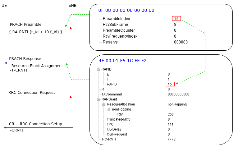
'RRC
Connection Request' and 'RRC Connection Setup' procedure can be
summerized as in following diagram. For the details, refer to http://www.sharetechnote.com/html/RACH_LTE.html
(The message contents shown in the box is only an example. The HEX
arrays you would see on your device and network would be different from
what you see
here. But overall structure should be similar to this)
Note
: This example shows the case where Contention Resolution and RRC
Connection Setup is being transmitted at a single step, but it is also
possible that Contention Resolution and RRC Connection Setup message is
transmitted as two separate process.
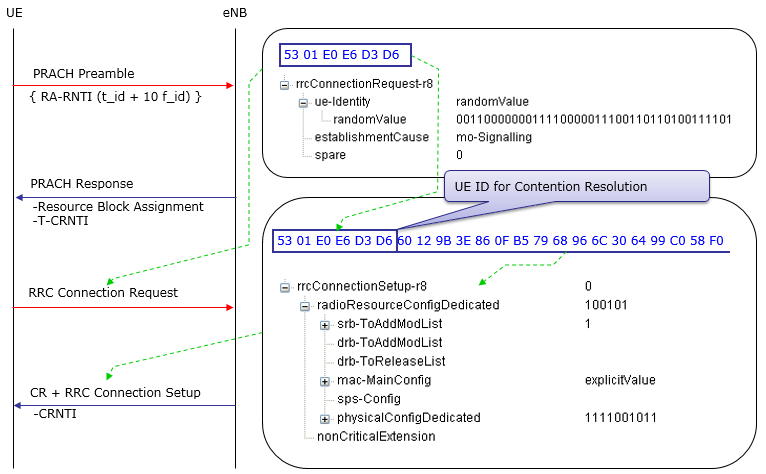
As
you see in the following diagram, the most important IE (infomration
element) in RRC Connection Setup message is
"RadioResourceConfigDedicated" under which you can setup SRB, DRB, MAC
and PHY config. Even thouth there is IEs related to DRB, in most case we
setup only SRBs in RRC Connection Setup. It is similar to WCDMA RRC
Connection setup message in which you usually setup only
SRB (Control Channel Part) even though there is IEs for RB(Data
Traffic).
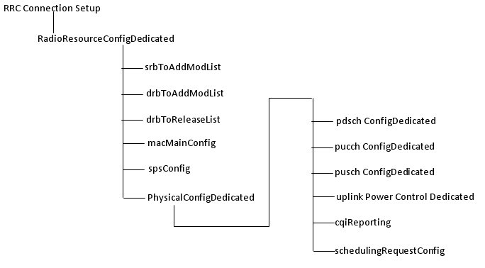
One
thing you have to notice is that you will find
"RadioResourceCondigDedicated" IE not only in RRC Connection Setup
message but also in RRC Connection Reconfiguration message. In that
case, you have to be careful so that the one you set in RRC Connection
Reconfig message properly match the one you set in RRC Connection Setup
message. It means that you have to understand the correlation
very clearly between RRC Connection Setup message and RRC Connection
Reconfig message. This is also very similar to WCDMA case.
One
example of RRC Connection Setup is as follows. As you see the contents
below, main purpose of RRC Connection Setup message is to specify the
MAC/RLC/PHY setup for SRB 0 and SRB 1 bearer. So if you make any mistake
in this message, Network or UE will fail to decode messages that comes
after this message.
Especially
you have to be very careful about PhysicalConfigDedicated part. If you
see one of the following issues after 'RRC Connection Setup', the first
thing you have to check is PhysicalConfigDedicated. (You have to check
all the detailed parameter and make it sure that UE properly decoded
those information and properly configure itself according to the
contents).
i) CRC Error for PUSCH
ii) UE log shows it transmit PUSCH, but Network log shows no PUSCH, not even CRC error
DL-CCCH-Message ::= SEQUENCE
+-message ::= CHOICE [c1]
+-c1 ::= CHOICE [rrcConnectionSetup]
+-rrcConnectionSetup ::= SEQUENCE
+-rrc-TransactionIdentifier ::= INTEGER (0..3) [0]
+-criticalExtensions ::= CHOICE [c1]
+-c1 ::= CHOICE [rrcConnectionSetup-r8]
+-rrcConnectionSetup-r8 ::= SEQUENCE [0]
+-radioResourceConfigDedicated ::= SEQUENCE [100101]
| +-srb-ToAddModList ::= SEQUENCE OF SIZE(1..2) [1] OPTIONAL:Exist
| | +-SRB-ToAddMod ::= SEQUENCE [11]
| | +-srb-Identity ::= INTEGER (1..2) [1]
| | +-rlc-Config ::= CHOICE [defaultValue] OPTIONAL:Exist
| | | +-defaultValue ::= NULL
| | +-logicalChannelConfig ::= CHOICE [defaultValue] OPTIONAL:Exist
| | +-defaultValue ::= NULL
| +-drb-ToAddModList ::= SEQUENCE OF OPTIONAL:Omit
| +-drb-ToReleaseList ::= SEQUENCE OF OPTIONAL:Omit
| +-mac-MainConfig ::= CHOICE [explicitValue] OPTIONAL:Exist
| | +-explicitValue ::= SEQUENCE [111]
| | +-ul-SCH-Config ::= SEQUENCE [11] OPTIONAL:Exist
| | | +-maxHARQ-Tx ::= ENUMERATED [n5] OPTIONAL:Exist
| | | +-periodicBSR-Timer ::= ENUMERATED [sf20] OPTIONAL:Exist
| | | +-retxBSR-Timer ::= ENUMERATED [sf320]
| | | +-ttiBundling ::= BOOLEAN [FALSE]
| | +-drx-Config ::= CHOICE [release] OPTIONAL:Exist
| | | +-release ::= NULL
| | +-timeAlignmentTimerDedicated ::= ENUMERATED [infinity]
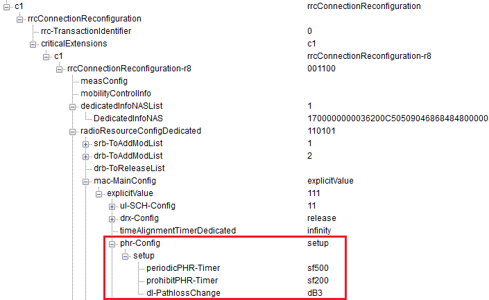
| | +-phr-Config ::= CHOICE [setup] OPTIONAL:Exist
| | +-setup ::= SEQUENCE
| | +-periodicPHR-Timer ::= ENUMERATED [sf500]
| | +-prohibitPHR-Timer ::= ENUMERATED [sf200]
| | +-dl-PathlossChange ::= ENUMERATED [dB3]
| +-sps-Config ::= SEQUENCE OPTIONAL:Omit
| +-physicalConfigDedicated ::= SEQUENCE [1111001011] OPTIONAL:Exist
| +-pdsch-ConfigDedicated ::= SEQUENCE OPTIONAL:Exist
| | +-p-a ::= ENUMERATED [dB-3]
| +-pucch-ConfigDedicated ::= SEQUENCE [0] OPTIONAL:Exist
| | +-ackNackRepetition ::= CHOICE [release]
| | | +-release ::= NULL
| | +-tdd-AckNackFeedbackMode ::= ENUMERATED OPTIONAL:Omit
| +-pusch-ConfigDedicated ::= SEQUENCE OPTIONAL:Exist
| | +-betaOffset-ACK-Index ::= INTEGER (0..15) [9]
| | +-betaOffset-RI-Index ::= INTEGER (0..15) [6]
| | +-betaOffset-CQI-Index ::= INTEGER (0..15) [6]
| +-uplinkPowerControlDedicated ::= SEQUENCE [1] OPTIONAL:Exist
| | +-p0-UE-PUSCH ::= INTEGER (-8..7) [0]
| | +-deltaMCS-Enabled ::= ENUMERATED [en0]
| | +-accumulationEnabled ::= BOOLEAN [TRUE]
| | +-p0-UE-PUCCH ::= INTEGER (-8..7) [0]
| | +-pSRS-Offset ::= INTEGER (0..15) [3]
| | +-filterCoefficient ::= ENUMERATED [fc4] OPTIONAL:Exist
| +-tpc-PDCCH-ConfigPUCCH ::= CHOICE OPTIONAL:Omit
| +-tpc-PDCCH-ConfigPUSCH ::= CHOICE OPTIONAL:Omit
| +-cqi-ReportConfig ::= SEQUENCE [10] OPTIONAL:Exist
| | +-cqi-ReportModeAperiodic ::= ENUMERATED [rm30] OPTIONAL:Exist
| | +-nomPDSCH-RS-EPRE-Offset ::= INTEGER (-1..6) [0]
| | +-cqi-ReportPeriodic ::= CHOICE OPTIONAL:Omit
| +-soundingRS-UL-ConfigDedicated ::= CHOICE OPTIONAL:Omit
| +-antennaInfo ::= CHOICE [defaultValue] OPTIONAL:Exist
| | +-defaultValue ::= NULL
| +-schedulingRequestConfig ::= CHOICE [setup] OPTIONAL:Exist
| +-setup ::= SEQUENCE
| +-sr-PUCCH-ResourceIndex ::= INTEGER (0..2047) [20]
| +-sr-ConfigIndex ::= INTEGER (0..155) [30]
| +-dsr-TransMax ::= ENUMERATED [n4]
+-nonCriticalExtension ::= SEQUENCE OPTIONAL:Omit
< Note 1 >
+-pdsch-ConfigDedicated ::= SEQUENCE OPTIONAL:Exist
| +-p-a ::= ENUMERATED [dB-3]
:
transmission power is calculated according to Section 5.2 of 3GPP
TS36.213 from the reference signal power and the values of the P_A and
P_B parameters specified for this procedure. These parameters set the
PDSCH transmission power differences between symbols with and without
RS.
Unproper
settings for this value would cause large amount of CRC errors on PDSCH
reception on UE side, resulting in a lot of HARQ NACK from UE.
< Note 2 >
If you see SRB-ToAddMod IE, you would see a couple of Default Value. What does this mean ?
Following two sections of 36.331 will give you the answer.
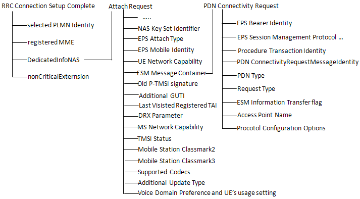
This
step would be one of very important steps during the initial
registration process mainly because UE send a lot of it's capability
information (especailly NAS layer capability information) to the core
network.
As you see this step carries two important NAS message as follows.
NAS : Attach Request
: The most important information carried by this message would be UE
capability in terms of ciphering and integrity. If you don't do proper
following step (especially at Attach accept step) based on the
information on this, UE will fail to registration. Even bigger problem
is that the failure
mode of registration varies depending UE protocol stack implementation.
So in many case it is very hard to find the root cause of the problem.
ESM : PDN Connectivity Request
: The most information of this message would be the protocol
configuration options (PCO). From this you can figure out what kind of
packet service UE support or want to get supported. If you don't
properly handle this information, it will also result in registration
failure and the
failure mode would vary depending on UE implementation.
Attach request ::= DIVISION
+-Security header type ::= V
| +-Security header type ::= CHOICE [Plain NAS message, not security protected]
+-EPS mobility management protocol discriminator ::= V
| +-Protocol discriminator ::= PD [7]
+-Attach request message identity ::= V
| +-Message type ::= MSG [41]
+-NAS key set identifier ::= V
| +-TSC ::= CHOICE [native security context (for KSI ASME)]
| +-NAS key set identifier ::= CHOICE [possible values for the NAS key set identifier 1]
+-EPS attach type ::= V
| +-Spare ::= FIX [0]
| +-EPS attach type value ::= CHOICE [EPS attach]
+-Old GUTI or IMSI ::= LV
| +-Octet1 ::= DIVISION
| | +-Length of EPS mobile identity contents ::= LEN (0..255) [11]
| +-Octet2 ::= DIVISION
| | +-Spare ::= FIX [F]
| | +-Odd/even indication ::= CHOICE [even number of identity digits and also when the GUTI is used]
| | +-Type of identity ::= CHOICE [GUTI]
| +-Octet3 ::= DIVISION
| | +-MCC digit 2 ::= INT (0..15) [0]
| | +-MCC digit 1 ::= INT (0..15) [0]
| +-Octet4 ::= DIVISION
| | +-MNC digit 3 ::= INT (0..15) [15]
| | +-MCC digit 3 ::= INT (0..15) [1]
| +-Octet5 ::= DIVISION
| | +-MNC digit 2 ::= INT (0..15) [1]
| | +-MNC digit 1 ::= INT (0..15) [0]
| +-Octet6 ::= DIVISION
| | +-MME Group ID ::= INT (0..255) [0]
| +-Octet7 ::= DIVISION
| | +-MME Group ID(continued) ::= INT (0..255) [1]
| +-Octet8 ::= DIVISION
| | +-MME Code ::= INT (0..255) [1]
| +-Octet9 ::= DIVISION
| | +-M-TMSI ::= INT (0..255) [18]
| +-Octet10 ::= DIVISION
| | +-M-TMSI(continued) ::= INT (0..255) [52]
| +-Octet11 ::= DIVISION
| | +-M-TMSI(continued) ::= INT (0..255) [86]
| +-Octet12 ::= DIVISION
| +-M-TMSI(continued) ::= INT (0..255) [120]
+-UE network capability ::= LV
| +-Octet1 ::= DIVISION
| | +-Length of UE network capability contents ::= LEN (0..255) [2]
| +-Octet2 ::= DIVISION
| | +-EEA0 ::= CHOICE [EPS encryption algorithm EEA0 supported]
| | +-128-EEA1 ::= CHOICE [EPS encryption algorithm 128-EEA1 supported]
| | +-128-EEA2 ::= CHOICE [EPS encryption algorithm 128-EEA2 supported]
| | +-EEA3 ::= CHOICE [EPS encryption algorithm EEA3 not supported]
| | +-EEA4 ::= CHOICE [EPS encryption algorithm EEA4 not supported]
| | +-EEA5 ::= CHOICE [EPS encryption algorithm EEA5 not supported]
| | +-EEA6 ::= CHOICE [EPS encryption algorithm EEA6 not supported]
| | +-EEA7 ::= CHOICE [EPS encryption algorithm EEA7 not supported]
| +-Octet3 ::= DIVISION
| | +-spare ::= FIX [0]
| | +-128-EIA1 ::= CHOICE [EPS integrity algorithm 128-EIA1 supported]
| | +-128-EIA2 ::= CHOICE [EPS integrity algorithm 128-EIA2 supported]
| | +-EIA3 ::= CHOICE [EPS integrity algorithm EIA3 not supported]
| | +-EIA4 ::= CHOICE [EPS integrity algorithm EIA4 not supported]
| | +-EIA5 ::= CHOICE [EPS integrity algorithm EIA5 not supported]
| | +-EIA6 ::= CHOICE [EPS integrity algorithm EIA6 not supported]
| | +-EIA7 ::= CHOICE [EPS integrity algorithm EIA7 not supported]
| +-Octet4 ::= DIVISION
| | +-UEA0 ::= CHOICE [UMTS encryption algorithm UEA0 not supported]
| | +-UEA1 ::= CHOICE [UMTS encryption algorithm UEA1 not supported]
| | +-UEA2 ::= CHOICE [UMTS encryption algorithm UEA2 not supported]
| | +-UEA3 ::= CHOICE [UMTS encryption algorithm UEA3 not supported]
| | +-UEA4 ::= CHOICE [UMTS encryption algorithm UEA4 not supported]
| | +-UEA5 ::= CHOICE [UMTS encryption algorithm UEA5 not supported]
| | +-UEA6 ::= CHOICE [UMTS encryption algorithm UEA6 not supported]
| | +-UEA7 ::= CHOICE [UMTS encryption algorithm UEA7 not supported]
| +-Octet5 ::= DIVISION
|
| +-UCS2 ::= CHOICE [The UE has a preference for the default alphabet
(defined in 3GPP TS 23.038 [3]) over UCS2 (see ISO/IEC 10646 [29])]
| | +-UIA1 ::= CHOICE [UMTS integrity algorithm UIA1 not supported]
| | +-UIA2 ::= CHOICE [UMTS integrity algorithm UIA2 not supported]
| | +-UIA3 ::= CHOICE [UMTS integrity algorithm UIA3 not supported]
| | +-UIA4 ::= CHOICE [UMTS integrity algorithm UIA4 not supported]
| | +-UIA5 ::= CHOICE [UMTS integrity algorithm UIA5 not supported]
| | +-UIA6 ::= CHOICE [UMTS integrity algorithm UIA6 not supported]
| | +-UIA7 ::= CHOICE [UMTS integrity algorithm UIA7 not supported]
| +-Octet6 ::= DIVISION
| | +-spare ::= FIX [0]
| | +-1xSRVCC ::= CHOICE [SRVCC from E-UTRAN to cdma2000 1xCS not supported]
| | +-spare ::= FIX [0]
| +-Octet7-14 ::= DIVISION
| +-Spare ::= OCTETARRAY SIZE(0..8) [00]
+-ESM message container ::= LV-E
| +-Octet1-Octet2 ::= DIVISION
| | +-Length of ESM message container ::= LEN (0..65535) [23]
| +-Octet3- ::= DIVISION
| +-ESM message container contents ::= OCTETARRAY SIZE(0..65535)
[0201D031D1271080000100000300000A00000C00000D00]
+-Old P-TMSI signature ::= TV OPTIONAL:Omit
| +-Octet1 ::= DIVISION
| | +-P-TMSI signature IEI ::= IEI [19]
| +-Octet2-4 ::= DIVISION
| +-P-TMSI signature value ::= INT (0..16777215) [0]
+-Additional GUTI ::= TLV OPTIONAL:Omit
| +-Octet1 ::= DIVISION
| | +-EPS mobile identity IEI ::= IEI [50]
| +-Octet2 ::= DIVISION
| | +-Length of mobile identity IEI ::= LEN (0..255) [1]
| +-Octet3 ::= DIVISION
| | +-Identity digit 1 ::= INT (0..15) [0]
| | +-Odd/even indication ::= CHOICE [even number of identity digits and also when the GUTI is used]
| | +-Type of identity ::= CHOICE [IMSI]
| +-Octet4 ::= DIVISION
| +-Identity digit p ::= OCTETARRAY SIZE(0..10)
+-Last visited registered TAI ::= TV OPTIONAL:Exist
| +-Octet1 ::= DIVISION
| | +-Tracking area identity IEI ::= IEI [52]
| +-Octet2 ::= DIVISION
| | +-MCC digit 2 ::= INT (0..15) [1]
| | +-MCC digit 1 ::= INT (0..15) [3]
| +-Octet3 ::= DIVISION
| | +-MNC digit 3 ::= INT (0..15) [0]
| | +-MCC digit 3 ::= INT (0..15) [1]
| +-Octet4 ::= DIVISION
| | +-MNC digit 2 ::= INT (0..15) [8]
| | +-MNC digit 1 ::= INT (0..15) [4]
| +-Octet5 ::= DIVISION
| | +-TAC ::= INT (0..255) [0]
| +-Octet6 ::= DIVISION
| +-TAC(continued) ::= INT (0..255) [1]
+-DRX parameter ::= TV OPTIONAL:Omit
+-MS network capability ::= TLV OPTIONAL:Omit
+-Old location area identification ::= TV OPTIONAL:Omit
+-TMSI status ::= TV OPTIONAL:Omit
+-Mobile Station Classmark 2 ::= TLV OPTIONAL:Omit
+-Mobile Station Classmark 3 ::= TLV OPTIONAL:Omit
+-Supported Codecs ::= TLV OPTIONAL:Omit
If you decode the ESM message container contents part, you will get the following contents.
NAS_LTE:ESM,PDN connectivity request
PDN connectivity request ::= DIVISION
+-EPS bearer identity ::= V
| +-EPS bearer identity value ::= CHOICE [No EPS bearer identity assigned]
+-EPS session management protocol discriminator ::= V
| +-Protocol discriminator ::= PD [2]
+-Procedure transaction identity ::= V
| +-Procedure transaction identity ::= CHOICE [Procedure transaction identity value 1]
+-PDN connectivity request message identity ::= V
| +-Message type ::= MSG [D0]
+-PDN type ::= V
| +-spare ::= FIX [0]
| +-PDN type value ::= CHOICE [IPv4v6]
+-Request type ::= V
| +-Spare ::= FIX [0]
| +-Request type value ::= CHOICE [initial request]
+-ESM information transfer flag ::= TV OPTIONAL:Exist
| +-Octet1 ::= DIVISION
| +-ESM information transfer flag IEI ::= IEI [D-]
| +-spare ::= FIX [0]
| +-EIT value ::= CHOICE [security protected ESM information transfer required]
+-Access point name ::= TLV OPTIONAL:Omit
| +-Octet1 ::= DIVISION
| | +-Access point name IEI ::= IEI [28]
| +-Octet2 ::= DIVISION
| | +-Length of access point name contents ::= LEN (0..255) [0]
| +-Octet3-Octet102 ::= DIVISION
| +-Access point name value ::= OCTETARRAY SIZE(0..100)
+-Protocol configuration options ::= TLV OPTIONAL:Exist
+-Octet1 ::= DIVISION
| +-Protocol configuration options IEI ::= IEI [27]
+-Octet2 ::= DIVISION
| +-Length of protocol config options contents ::= LEN (0..255) [16]
+-Octet3 ::= DIVISION
| +-ext ::= EXT1 [1]
| +-spare ::= FIX [0]
| +-Configuration protocol ::= CHOICE [PPP for use with IP PDP type]
+-Octet4-Octet253 ::= DIVISION
+-protocol config options contents ::= OCTETARRAY SIZE(0..250) [000100000300000A00000C00000D00]
There are couple of important information in this message as described below.
ESM information transfer flag :
According to Step 9a1 of Table 4.5.2.3-1: UE registration procedure
(state 1 to state 2) of 36.508, Network has to go through ESM :
Information Request as described below.
IF
the UE sets the ESM information transfer flag in the last PDN
CONNECTIVITY REQUEST message THEN the SS transmits an ESM INFORMATION
REQUEST message to initiate exchange of protocol configuration options
and/or APN
PDN Type
: specifies IP version that the UE wants to use for EPS Bearer and
Network may or may not use the same IP version in Default (or Dedicated)
EPS Bearer Context Request. Some UE would accept whatever IP version is
specified by the network at EPS Bearer establishment step, but some UE
fail to setup EPS bearer
if the IP version Network specify in Default (or Dedicated) EPS Bearer
Context Request does not match the PDN type in this message.
Access Point Name : UE
shows many different behavior related to this APN name. Followings are
some of the behavior that I observed from a couple of difference
devices.
i) UE does not specify any APN here and accept whatever Network specifies in Activate Default EPS Bearer Context Request.
ii) UE specify a specific APN here, but it accept whatever Network specifies in Activate Default EPS Bearer Context Request.
iii)
UE specify a specific APN here, but it reject the APN that Network
specifies in Activate Default EPS Bearer Context Request if it is
different from what UE specified here.
Protocol Configuration Options
: You can get the detailed information from this protocol config
options contents from TS24_008 10.5.6.3 Protocol configuration options
which can be summarized as follows.
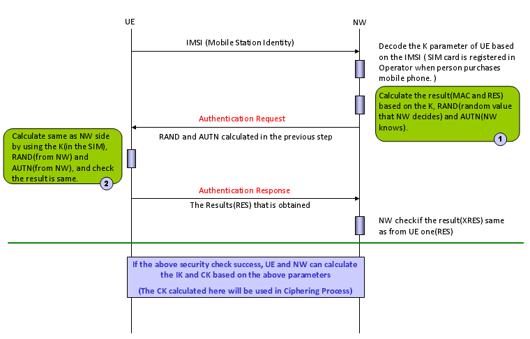
RRC : UL Information Transfer + NAS : Authentication Response
"Authentication"
process is a process similar to 'log in' process when you use a
computer. In C2K and GSM, this authentication process is
'uni-directional', meaning that only Network authenticate UE and UE does
not authenticate the network. As you may easily guess, this would cause
a serious security problem. If I make a fake network which accept any
UE, I can cheat a UE to camp
on the fake network rather than the one the UE is supposed to camp on
to. (But this kind of 'uni directional' authentication would make it so
easy to test a UE using network simulator -:)
To
improve this security issues, in LTE (in WCDMA as well) they do
'bi-directional' authentication, meaning that UE has to pass the
authentication process and Newtork also has to pass the process as well.
The overall authentication process is as follows.
There are three main components of this authentication process :
i) Input Parameters
ii) Authentication Algorithm
iii) Output Values (calcuated by Authentication Algorithm using the Input Parameters).
Both
UE and Network uses the same Input Parameters and the same
Authentication Algorithms, so they both should produce the same Output
Values, otherwise Authentication fails.
One
thing you have to keep in mind is that UE and Network exchange only
Input Parameters and Output values, not the authentication Algorithm.
Authentication Algorithm on UE side is stored in USIM and Authentication
Algorithm on NW side is stored in Authentication Center. Both UE and NW
just assume that they would use the identical algorithms.
Normally
use use diffent Authentication Algorithm for testing and for live
network. The most commonly used algorithm for testing is what we
often call "Dummy XOR" algorithm which is defined in 36.508 section 4.9 Common test USIM parameters for LTE and 34.408 section 8 Test USIM Parameters for WCDMA.
The most common used algorithm in live network (as far as I know) is Milenage algorithm.
One
example of Authentication Request and Authentication Response is as
follows. You would notice that RAND, AUTN are carried by Authentication
Request message and RES value is carried by Authentication Response.
NAS_LTE:EMM,Authentication request
Authentication request ::= DIVISION
+-Security header type ::= V
| +-Security header type ::= CHOICE [Plain NAS message, not security protected]
+-EPS mobility management protocol discriminator ::= V
| +-Protocol discriminator ::= PD [7]
+-Authentication request message type ::= V
| +-Message type ::= MSG [52]
+-Spare half octet ::= V
| +-Spare half octet ::= FIX [0]
+-NAS key set identifier ASME ::= V
| +-TSC ::= CHOICE [native security context (for KSI ASME)]
| +-NAS key set identifier ::= CHOICE [possible values for the NAS key set identifier 0]
+-Authentication parameter RAND ::= V
| +-Octet1-Octet16 ::= DIVISION
| +-RAND value ::= OCTETARRAY SIZE(16..16) [A3DE0C6D363E30C364A4078F1BF8D577]
+-Authentication parameter AUTN ::= LV
+-Octet1 ::= DIVISION
| +-Length of AUTN contents ::= LEN (0..255) [16]
+-Octet2-Octet17 ::= DIVISION
+-AUTN ::= OCTETARRAY SIZE(0..16) [5E726B56B4EC9001A3CF2E5E726BC6B5]
NAS_LTE:EMM,Authentication response
Authentication response ::= DIVISION
+-Security header type ::= V
| +-Security header type ::= CHOICE [Plain NAS message, not security protected]
+-EPS mobility management protocol discriminator ::= V
| +-Protocol discriminator ::= PD [7]
+-Authentication response message identity ::= V
| +-Message type ::= MSG [53]
+-Authentication response parameter ::= LV
+-Octet1 ::= DIVISION
| +-Length of Authentication response parameter contents ::= LEN (0..255) [8]
+-Octet2-17 ::= DIVISION
+-RES ::= OCTETARRAY SIZE(0..16) [A3CF2E5E726B56B4]
Security Mode Command message to inform the UE of the following information (instructions).
i) I (Newtork) am capable of these kinds of ciphering (encryption) algorithms
ii) I (Newtork) am capable of these kinds of integrity algorithms
iii)
Among those ciphering algorithm which I am capable of, I will be using
"this specific algorithm" for the communication with you (UE).
iv)
Among those integrity algorithm which I am capable of, I will be using
"this specific algorithm" for the communication with you (UE)
In
LTE, they are using separate Security Mode process for NAS and RRC,
whereas in WCDMA only one security mode process (RRC only) was used (NAS
is indirectly protected since NAS message was embedded in RRC and
protected as a part of RRC message). The part marked in blue is for item
i) and ii) listed above and the part marked in red is for item iii) and
iv).
NAS_LTE:EMM,Security mode command
Security mode command ::= DIVISION
+-Security header type ::= V
| +-Security header type ::= CHOICE [Plain NAS message, not security protected]
+-EPS mobility management protocol discriminator ::= V
| +-Protocol discriminator ::= PD [7]
+-Security mode command message identity ::= V
| +-Message type ::= MSG [5D]
+-Selected NAS security algorithms ::= V
| +-Octet1 ::= DIVISION
| +-spare ::= FIX [0]
| +-Type of ciphering algorithm ::= CHOICE [EPS encryption algorithm EEA0(ciphering not used)]
| +-spare ::= FIX [0]
| +-Type of integrity protection algorithm ::= CHOICE [Reserved 0]
+-Spare half octet ::= V
| +-Spare half octet ::= FIX [0]
+-NAS key set identifier ::= V
| +-TSC ::= CHOICE [native security context (for KSI ASME)]
| +-NAS key set identifier ::= CHOICE [possible values for the NAS key set identifier 0]
+-Replayed UE security capabilities ::= LV
| +-Octet1 ::= DIVISION
| | +-Length of UE security capability contents ::= LEN (0..255) [2]
| +-Octet2 ::= DIVISION
| | +-EEA0 ::= CHOICE [EPS encryption algorithm EEA0 supported]
| | +-128-EEA1 ::= CHOICE [EPS encryption algorithm 128-EEA1 supported]
| | +-128-EEA2 ::= CHOICE [EPS encryption algorithm 128-EEA2 supported]
| | +-EEA3 ::= CHOICE [EPS encryption algorithm EEA3 not supported]
| | +-EEA4 ::= CHOICE [EPS encryption algorithm EEA4 not supported]
| | +-EEA5 ::= CHOICE [EPS encryption algorithm EEA5 not supported]
| | +-EEA6 ::= CHOICE [EPS encryption algorithm EEA6 not supported]
| | +-EEA7 ::= CHOICE [EPS encryption algorithm EEA7 not supported]
| +-Octet3 ::= DIVISION
| | +-spare ::= FIX [1]
| | +-128-EIA1 ::= CHOICE [EPS integrity algorithm 128-EIA1 supported]
| | +-128-EIA2 ::= CHOICE [EPS integrity algorithm 128-EIA2 supported]
| | +-EIA3 ::= CHOICE [EPS integrity algorithm EIA3 not supported]
| | +-EIA4 ::= CHOICE [EPS integrity algorithm EIA4 not supported]
| | +-EIA5 ::= CHOICE [EPS integrity algorithm EIA5 not supported]
| | +-EIA6 ::= CHOICE [EPS integrity algorithm EIA6 not supported]
| | +-EIA7 ::= CHOICE [EPS integrity algorithm EIA7 not supported]
| +-Octet4 ::= DIVISION
| | +-UEA0 ::= CHOICE [UMTS encryption algorithm UEA0 not supported]
| | +-UEA1 ::= CHOICE [UMTS encryption algorithm UEA1 not supported]
| | +-UEA2 ::= CHOICE [UMTS encryption algorithm UEA2 not supported]
| | +-UEA3 ::= CHOICE [UMTS encryption algorithm UEA3 not supported]
| | +-UEA4 ::= CHOICE [UMTS encryption algorithm UEA4 not supported]
| | +-UEA5 ::= CHOICE [UMTS encryption algorithm UEA5 not supported]
| | +-UEA6 ::= CHOICE [UMTS encryption algorithm UEA6 not supported]
| | +-UEA7 ::= CHOICE [UMTS encryption algorithm UEA7 not supported]
| +-Octet5 ::= DIVISION
| | +-spare ::= FIX [0]
| | +-UIA1 ::= CHOICE [UMTS integrity algorithm UIA1 not supported]
| | +-UIA2 ::= CHOICE [UMTS integrity algorithm UIA2 not supported]
| | +-UIA3 ::= CHOICE [UMTS integrity algorithm UIA3 not supported]
| | +-UIA4 ::= CHOICE [UMTS integrity algorithm UIA4 not supported]
| | +-UIA5 ::= CHOICE [UMTS integrity algorithm UIA5 not supported]
| | +-UIA6 ::= CHOICE [UMTS integrity algorithm UIA6 not supported]
| | +-UIA7 ::= CHOICE [UMTS integrity algorithm UIA7 not supported]
| +-Octet6 ::= DIVISION
| +-spare ::= FIX [0]
| +-GEA1 ::= CHOICE [GPRS encryption algorithm GEA1 not supported]
| +-GEA2 ::= CHOICE [GPRS encryption algorithm GEA2 not supported]
| +-GEA3 ::= CHOICE [GPRS encryption algorithm GEA3 not supported]
| +-GEA4 ::= CHOICE [GPRS encryption algorithm GEA4 not supported]
| +-GEA5 ::= CHOICE [GPRS encryption algorithm GEA5 not supported]
| +-GEA6 ::= CHOICE [GPRS encryption algorithm GEA6 not supported]
| +-GEA7 ::= CHOICE [GPRS encryption algorithm GEA7 not supported]
+-IMEISV request ::= TV OPTIONAL:Omit
| +-Octet1 ::= DIVISION
| +-IMEISV request IEI ::= IEI [C-]
| +-spare ::= FIX [0]
| +-IMEISV request value ::= CHOICE [IMEISV not requested]
+-Replayed nonce UE ::= TV OPTIONAL:Omit
| +-Octet1 ::= DIVISION
| | +-Nonce IEI ::= IEI [55]
| +-Octet2-Octet5 ::= DIVISION
| +-Nonce value ::= OCTETARRAY SIZE(4..4) [00000000]
+-Nonce MME ::= TV OPTIONAL:Omit
+-Octet1 ::= DIVISION
| +-Nonce IEI ::= IEI [56]
+-Octet2-Octet5 ::= DIVISION
+-Nonce value ::= OCTETARRAY SIZE(4..4) [00000000]
Security
Mode Complete is the answer to "Security Mode Command" message, so it
is simple. If UE is also capable of the Integrity, Security algorithm
that NW want to use, it send 'Security Mode Complete', if UE is not
capable of them, it send 'Security Mode Failure'.
NAS_LTE:EMM,Security mode complete
Security mode complete ::= DIVISION
+-Security header type ::= V
| +-Security header type ::= CHOICE [Plain NAS message, not security protected]
+-EPS mobility management protocol discriminator ::= V
| +-Protocol discriminator ::= PD [7]
+-Security mode complete message identity ::= V
| +-Message type ::= MSG [5E]
+-IMEISV ::= TLV OPTIONAL:Omit
+-Octet1 ::= DIVISION
| +-Mobile Identity IEI ::= IEI [23]
+-Octet2 ::= DIVISION
| +-Length of mobile identity contents ::= LEN (0..255) [0]
+-Octet3 ::= DIVISION
| +-Identity digit 1 ::= INT (0..15) [0]
| +-Odd/even indication ::= CHOICE [even number of identity digits and also when the TMSI/P-TMSI is used]
| +-Type of identity ::= CHOICE [No Identity]
+-Octet4-Octet11 ::= DIVISION
+-Identity digit p ::= OCTETARRAY SIZE(0..8)
This is the same step as NAS:Security Mode Command, the only difference is that this is only for RRC message.
RRC_LTE:DL-DCCH-Message
DL-DCCH-Message ::= SEQUENCE
+-message ::= CHOICE [c1]
+-c1 ::= CHOICE [securityModeCommand]
+-securityModeCommand ::= SEQUENCE
+-rrc-TransactionIdentifier ::= INTEGER (0..3) [0]
+-criticalExtensions ::= CHOICE [c1]
+-c1 ::= CHOICE [securityModeCommand-r8]
+-securityModeCommand-r8 ::= SEQUENCE [0]
+-securityConfigSMC ::= SEQUENCE
| +-securityAlgorithmConfig ::= SEQUENCE
| +-cipheringAlgorithm ::= ENUMERATED [eea1]
| +-integrityProtAlgorithm ::= ENUMERATED [eia1]
+-nonCriticalExtension ::= SEQUENCE OPTIONAL:Omit
- For Ciphering Algorithm Paramter, refer to EEA page.
- For Integrity Algorithm Paramter, refer to EIA page.
Security
Mode Complete is the answer to "Security Mode Command" message, so it
is simple. If UE is also capable of the Integrity, Security algorithm
that NW want to use, it send 'Security Mode Complete', if UE is not
capable of them, it send 'Security Mode Failure'.
UL-DCCH-Message ::= SEQUENCE
+-message ::= CHOICE [c1]
+-c1 ::= CHOICE [securityModeComplete]
+-securityModeComplete ::= SEQUENCE
+-rrc-TransactionIdentifier ::= INTEGER (0..3) [0]
+-criticalExtensions ::= CHOICE [securityModeComplete-r8]
+-securityModeComplete-r8 ::= SEQUENCE [0]
+-nonCriticalExtension ::= SEQUENCE OPTIONAL:Omit
As
the diversity of mobile services gets wider, Network needs to know
exact capability of a UE to provide proper services for each UE. For
example, what if network triggers an interRAT handover to a UE which
does not support that capability ? It would lead to communication drop.
In
case of WCDMA, Network can figure out all the details of UE capability
during RRC Connection Setup Complete message since UE report all the
details of its capability in RRC Connection Setup Complete message.
However, LTE RRC Connection Setup Complete message does not carry this
kind of information. In stead, LTE designed a new message dedicated for
investigating UE capability. This is the role of UE Capability Enquiry
and UE Capability Information message.
Strictly speaking, this is a kind of optional step.. but it is becoming more and more critical steps as LTE service evolves.
Following
is one example of ue-CapabilityRequest message and this is saying
"Report all of your LTE capability and UTRA capability".
DL-DCCH-Message ::= SEQUENCE
+-message ::= CHOICE [c1]
+-c1 ::= CHOICE [ueCapabilityEnquiry]
+-ueCapabilityEnquiry ::= SEQUENCE
+-rrc-TransactionIdentifier ::= INTEGER (0..3) [0]
+-criticalExtensions ::= CHOICE [c1]
+-c1 ::= CHOICE [ueCapabilityEnquiry-r8]
+-ueCapabilityEnquiry-r8 ::= SEQUENCE [0]
+-ue-CapabilityRequest ::= SEQUENCE OF SIZE(1..maxRAT-Capabilities[8]) [2]
| +-RAT-Type ::= ENUMERATED [eutra]
| +-RAT-Type ::= ENUMERATED [utra]
+-nonCriticalExtension ::= SEQUENCE OPTIONAL:Omit
This
message is the response to UE Capability Request message and it carries
all the details of UE capability. Since this is very complicated
message which has wide variety, I made a separate page for UE Capability Information.
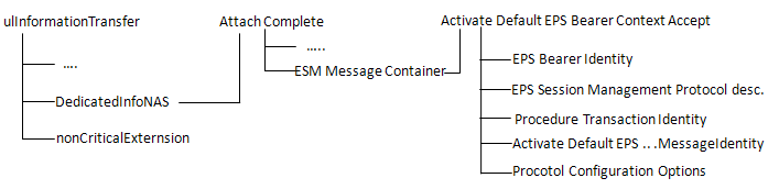
An important procedure done in this step is "ESM : Activate Default EPS Bearer Context Request".
One
thing you notice here is that in LTE Packet call is initiated by
Network where as in UMST most of the packet call is initiated by UE.
Network specifies an IP for the UE here.
If
you have any experience with WCDMA protocol, you may take this message
to be similar to 'Radio Bearer Setup' + 'Attach Accept' + Activate PDP
Context Accept.
At
this step, UE gets an IP from the network and this IP does not get
returned to Network even after 'RRC connection Release' and UE gets into
IDLE mode.
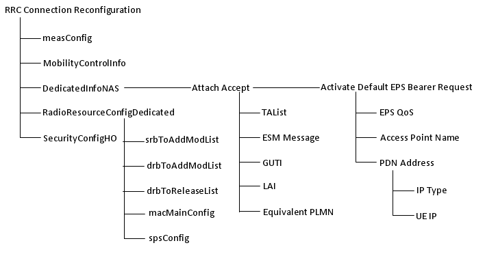
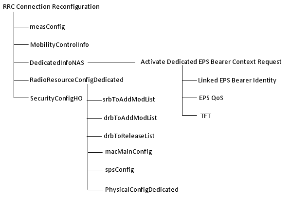
An
example of RRC Connection Reconfiguration is as follows. Don't try to
look into all the details since this message is one of the most
complicated message in LTE. Just try to understand overall structure and
compare the tree map shown above and the real messages shown below.
Probably it will take several month to understand all the details of these elements, so don't be so hurry.
Whenever
you study a little bit further details of the topics in the tree
diagram shown above, open up this section and see the details under the
topics you studied. If you fully understand all the information elements
shown below, you can say you mastered the LTE. Again don't try to
understand all of these at once. It will just raise your blood
pressure. Just look through these items as often as possible and get
familiar with the overall structure first.
DL-DCCH-Message ::= SEQUENCE
+-message ::= CHOICE [c1]
+-c1 ::= CHOICE [rrcConnectionReconfiguration]
+-rrcConnectionReconfiguration ::= SEQUENCE
+-rrc-TransactionIdentifier ::= INTEGER (0..3) [0]
+-criticalExtensions ::= CHOICE [c1]
+-c1 ::= CHOICE [rrcConnectionReconfiguration-r8]
+-rrcConnectionReconfiguration-r8 ::= SEQUENCE [001100]
+-measConfig ::= SEQUENCE OPTIONAL:Omit
+-mobilityControlInfo ::= SEQUENCE OPTIONAL:Omit
+-dedicatedInfoNASList ::= SEQUENCE OF SIZE(1..maxDRB[11]) [1] OPTIONAL:Exist
|
+-DedicatedInfoNAS ::= OCTET STRING SIZE(ALIGNED)
[074201E0060000F1100001002C5201C101091003777777
07616E726974737503636F6D05010A012037270E808021
0A0300000A81060A000001500BF600F11080010100000001]
+-radioResourceConfigDedicated ::= SEQUENCE [110101] OPTIONAL:Exist
| +-srb-ToAddModList ::= SEQUENCE OF SIZE(1..2) [1] OPTIONAL:Exist
| | +-SRB-ToAddMod ::= SEQUENCE [11]
| | +-srb-Identity ::= INTEGER (1..2) [2]
| | +-rlc-Config ::= CHOICE [defaultValue] OPTIONAL:Exist
| | | +-defaultValue ::= NULL
| | +-logicalChannelConfig ::= CHOICE [defaultValue] OPTIONAL:Exist
| | +-defaultValue ::= NULL
| +-drb-ToAddModList ::= SEQUENCE OF SIZE(1..maxDRB[11]) [1] OPTIONAL:Exist
| | +-DRB-ToAddMod ::= SEQUENCE [11111]
| | +-eps-BearerIdentity ::= INTEGER (0..15) [5] OPTIONAL:Exist
| | +-drb-Identity ::= INTEGER (1..32) [1]
| | +-pdcp-Config ::= SEQUENCE [101] OPTIONAL:Exist
| | | +-discardTimer ::= ENUMERATED [infinity] OPTIONAL:Exist
| | | +-rlc-AM ::= SEQUENCE OPTIONAL:Omit
| | | +-rlc-UM ::= SEQUENCE OPTIONAL:Exist
| | | | +-pdcp-SN-Size ::= ENUMERATED [len12bits]
| | | +-headerCompression ::= CHOICE [notUsed]
| | | +-notUsed ::= NULL
| | +-rlc-Config ::= CHOICE [um-Bi-Directional] OPTIONAL:Exist
| | | +-um-Bi-Directional ::= SEQUENCE
| | | +-ul-UM-RLC ::= SEQUENCE
| | | | +-sn-FieldLength ::= ENUMERATED [size10]
| | | +-dl-UM-RLC ::= SEQUENCE
| | | +-sn-FieldLength ::= ENUMERATED [size10]
| | | +-t-Reordering ::= ENUMERATED [ms50]
| | +-logicalChannelIdentity ::= INTEGER (3..10) [3] OPTIONAL:Exist
| | +-logicalChannelConfig ::= SEQUENCE [1] OPTIONAL:Exist
| | +-ul-SpecificParameters ::= SEQUENCE [1] OPTIONAL:Exist
| | +-priority ::= INTEGER (1..16) [13]
| | +-prioritisedBitRate ::= ENUMERATED [infinity]
| | +-bucketSizeDuration ::= ENUMERATED [ms100]
| | +-logicalChannelGroup ::= INTEGER (0..3) [2] OPTIONAL:Exist
| +-drb-ToReleaseList ::= SEQUENCE OF OPTIONAL:Omit
| +-mac-MainConfig ::= CHOICE [explicitValue] OPTIONAL:Exist
| | +-explicitValue ::= SEQUENCE [111]
| | +-ul-SCH-Config ::= SEQUENCE [11] OPTIONAL:Exist
| | | +-maxHARQ-Tx ::= ENUMERATED [n5] OPTIONAL:Exist
| | | +-periodicBSR-Timer ::= ENUMERATED [sf20] OPTIONAL:Exist
| | | +-retxBSR-Timer ::= ENUMERATED [sf320]
| | | +-ttiBundling ::= BOOLEAN [FALSE]
| | +-drx-Config ::= CHOICE [release] OPTIONAL:Exist
| | | +-release ::= NULL
| | +-timeAlignmentTimerDedicated ::= ENUMERATED [infinity]
| | +-phr-Config ::= CHOICE [setup] OPTIONAL:Exist
| | +-setup ::= SEQUENCE
| | +-periodicPHR-Timer ::= ENUMERATED [sf500]
| | +-prohibitPHR-Timer ::= ENUMERATED [sf200]
| | +-dl-PathlossChange ::= ENUMERATED [dB3]
| +-sps-Config ::= SEQUENCE OPTIONAL:Omit
| +-physicalConfigDedicated ::= SEQUENCE [0000110010] OPTIONAL:Exist
| +-pdsch-ConfigDedicated ::= SEQUENCE OPTIONAL:Omit
| +-pucch-ConfigDedicated ::= SEQUENCE OPTIONAL:Omit
| +-pusch-ConfigDedicated ::= SEQUENCE OPTIONAL:Omit
| +-uplinkPowerControlDedicated ::= SEQUENCE OPTIONAL:Omit
| +-tpc-PDCCH-ConfigPUCCH ::= CHOICE [setup] OPTIONAL:Exist
| | +-setup ::= SEQUENCE
| | +-tpc-RNTI ::= BIT STRING SIZE(16) [0000001111111111]
| | +-tpc-Index ::= CHOICE [indexOfFormat3]
| | +-indexOfFormat3 ::= INTEGER (1..15) [1]
| +-tpc-PDCCH-ConfigPUSCH ::= CHOICE [setup] OPTIONAL:Exist
| | +-setup ::= SEQUENCE
| | +-tpc-RNTI ::= BIT STRING SIZE(16) [0000000111111010]
| | +-tpc-Index ::= CHOICE [indexOfFormat3]
| | +-indexOfFormat3 ::= INTEGER (1..15) [1]
| +-cqi-ReportConfig ::= SEQUENCE OPTIONAL:Omit
| +-soundingRS-UL-ConfigDedicated ::= CHOICE OPTIONAL:Omit
| +-antennaInfo ::= CHOICE [explicitValue] OPTIONAL:Exist
| | +-explicitValue ::= SEQUENCE [0]
| | +-transmissionMode ::= ENUMERATED [tm1]
| | +-codebookSubsetRestriction ::= CHOICE OPTIONAL:Omit
| | +-ue-TransmitAntennaSelection ::= CHOICE [release]
| | +-release ::= NULL
| +-schedulingRequestConfig ::= CHOICE OPTIONAL:Omit
+-securityConfigHO ::= SEQUENCE OPTIONAL:Omit
+-nonCriticalExtension ::= SEQUENCE OPTIONAL:Omit
Even
though the decoded message shown above looks very complicated already,
it is not fully decoded. It shows only RRC part decode. If you decode
the NAS part in this message, you will get the following contents.
One
very important thing you have to keep in mind is that you have to
carefully populate this message so that I can properly handles/matches
the information sent from UE via Attach Request, otherwise this would
lead to registration failure.
AS_LTE:EMM,Attach accept
Attach accept ::= DIVISION
+-Security header type ::= V
| +-Security header type ::= CHOICE [Plain NAS message, not security protected]
+-EPS mobility management protocol discriminator ::= V
| +-Protocol discriminator ::= PD [7]
+-Attach accept message identity ::= V
| +-Message type ::= MSG [42]
+-Spare half octet ::= V
| +-Spare half octet ::= FIX [0]
+-EPS attach result ::= V
| +-Spare ::= FIX [0]
| +-EPS attach result value ::= CHOICE [EPS only]
+-T3412 value ::= V
| +-Octet1 ::= DIVISION
| +-Unit ::= CHOICE [value indicates that the timer is deactivated]
| +-Timer value ::= INT (0..31) [0]
+-TAI list ::= LV
| +-Octet1 ::= DIVISION
| | +-Length of tracking area identity list contents ::= LEN (0..255) [6]
| +-Octet2-97 ::= DIVISION
| +-tracking area identity list contents ::= OCTETARRAY SIZE(0..96) [0000F1100001]
+-ESM message container ::= LV-E
| +-Octet1-Octet2 ::= DIVISION
| | +-Length of ESM message container ::= LEN (0..65535) [44]
| +-Octet3- ::= DIVISION
|
+-ESM message container contents ::= OCTETARRAY SIZE(0..65535)
[5201C10109100377777707616E726974737503636F6D
05010A012037270E8080210A0300000A81060A000001]
+-GUTI ::= TLV OPTIONAL:Exist
| +-Octet1 ::= DIVISION
| | +-EPS mobile identity IEI ::= IEI [50]
| +-Octet2 ::= DIVISION
| | +-Length of EPS mobile identity contents ::= LEN (0..255) [11]
| +-Octet3 ::= DIVISION
| | +-Spare ::= FIX [F]
| | +-Odd/even indication ::= CHOICE [even number of identity digits and also when the GUTI is used]
| | +-Type of identity ::= CHOICE [GUTI]
| +-Octet4 ::= DIVISION
| | +-MCC digit 2 ::= INT (0..15) [0]
| | +-MCC digit 1 ::= INT (0..15) [0]
| +-Octet5 ::= DIVISION
| | +-MNC digit 3 ::= INT (0..15) [15]
| | +-MCC digit 3 ::= INT (0..15) [1]
| +-Octet6 ::= DIVISION
| | +-MNC digit 2 ::= INT (0..15) [1]
| | +-MNC digit 1 ::= INT (0..15) [0]
| +-Octet7 ::= DIVISION
| | +-MME Group ID ::= INT (0..255) [128]
| +-Octet8 ::= DIVISION
| | +-MME Group ID(continued) ::= INT (0..255) [1]
| +-Octet9 ::= DIVISION
| | +-MME Code ::= INT (0..255) [1]
| +-Octet10 ::= DIVISION
| | +-M-TMSI ::= INT (0..255) [0]
| +-Octet11 ::= DIVISION
| | +-M-TMSI(continued) ::= INT (0..255) [0]
| +-Octet12 ::= DIVISION
| | +-M-TMSI(continued) ::= INT (0..255) [0]
| +-Octet13 ::= DIVISION
| +-M-TMSI(continued) ::= INT (0..255) [1]
+-Location area identification ::= TV OPTIONAL:Omit
| +-Octet1 ::= DIVISION
| | +-Location Area Identification IEI ::= IEI [13]
| +-Octet2 ::= DIVISION
| | +-MCC digit 2 ::= INT (0..15) [0]
| | +-MCC digit 1 ::= INT (0..15) [0]
| +-Octet3 ::= DIVISION
| | +-MNC digit 3 ::= INT (0..15) [0]
| | +-MCC digit 3 ::= INT (0..15) [0]
| +-Octet4 ::= DIVISION
| | +-MNC digit 2 ::= INT (0..15) [0]
| | +-MNC digit 1 ::= INT (0..15) [0]
| +-Octet5 ::= DIVISION
| | +-LAC ::= INT (0..255) [0]
| +-Octet6 ::= DIVISION
| +-LAC (continued) ::= INT (0..255) [0]
+-MS identity ::= TLV OPTIONAL:Omit
| +-Octet1 ::= DIVISION
| | +-Mobile Identity IEI ::= IEI [23]
| +-Octet2 ::= DIVISION
| | +-Length of mobile identity contents ::= LEN (0..255) [0]
| +-Octet3 ::= DIVISION
| | +-Identity digit 1 ::= INT (0..15) [0]
| | +-Odd/even indication ::= CHOICE [even number of identity digits and also when the TMSI/P-TMSI is used]
| | +-Type of identity ::= CHOICE [No Identity]
| +-Octet4-Octet10 ::= DIVISION
| +-Identity digit p ::= OCTETARRAY SIZE(0..7)
+-EMM cause ::= TV OPTIONAL:Omit
| +-Octet1 ::= DIVISION
| | +-EMM cause IEI ::= IEI [53]
| +-Octet2 ::= DIVISION
| +-Cause value ::= CHOICE [#2:IMSI unknown in HSS]
+-T3402 value ::= TV OPTIONAL:Omit
| +-Octet1 ::= DIVISION
| | +-GPRS Timer IEI ::= IEI [17]
| +-Octet2 ::= DIVISION
| +-Unit ::= CHOICE [value is incremented in multiples of 2 seconds]
| +-Timer value ::= INT (0..31) [0]
+-T3423 value ::= TV OPTIONAL:Omit
| +-Octet1 ::= DIVISION
| | +-GPRS Timer IEI ::= IEI [59]
| +-Octet2 ::= DIVISION
| +-Unit ::= CHOICE [value is incremented in multiples of 2 seconds]
| +-Timer value ::= INT (0..31) [0]
+-Equivalent PLMNs ::= TLV OPTIONAL:Omit
| +-Octet1 ::= DIVISION
| | +-PLMN List IEI ::= IEI [4A]
| +-Octet2 ::= DIVISION
| | +-Length of PLMN List contents ::= LEN (0..255) [0]
| +-Octet3 ::= DIVISION
| | +-MCC digit 2 PLMN 1 ::= INT (0..15) [0]
| | +-MCC digit 1 PLMN 1 ::= INT (0..15) [0]
..... Octet 4 - Octet 45 .....
| +-Octet46 ::= DIVISION
| | +-MNC digit 3 PLMN 15 ::= INT (0..15) [0]
| | +-MCC digit 3 PLMN 15 ::= INT (0..15) [0]
| +-Octet47 ::= DIVISION
| +-MNC digit 2 PLMN 15 ::= INT (0..15) [0]
| +-MNC digit 1 PLMN 15 ::= INT (0..15) [0]
+-Emergency Number List ::= TLV OPTIONAL:Omit
| +-Octet1 ::= DIVISION
| | +-Emergency Number List IEI ::= IEI [34]
| +-Octet2 ::= DIVISION
| | +-Length of Emergency Number List IE contents ::= LEN (0..255) [0]
| +-Octet3-50 ::= DIVISION
| +-Emergency Number List IE contents ::= OCTETARRAY SIZE(0..48)
+-EPS network feature support ::= TLV OPTIONAL:Omit
| +-Octet1 ::= DIVISION
| | +-EPS network feature support IEI ::= IEI [64]
| +-Octet2 ::= DIVISION
| | +-Length of EPS network feature support contents ::= LEN (0..255) [0]
| +-Octet3 ::= DIVISION
| +-Spare ::= FIX [0]
| +-IMS VoPS ::= CHOICE [IMS voice over PS session in S1 mode not supported]
+-Additional update result ::= TV OPTIONAL:Omit
+-Octet1 ::= DIVISION
+-Additional update result IEI ::= IEI [F-]
+-Spare ::= FIX [0]
+-Additional update result value ::= CHOICE [no additional information]
If
you see the contents shown above, you would see "ESM message container
contents", which can be further decoded as below. The IE (information
element) marked in blue would be the most important IEs for UE
connection to data service application.
NAS_LTE:ESM,Activate default EPS bearer context request
Activate default EPS bearer context request ::= DIVISION
+-EPS bearer identity ::= V
| +-EPS bearer identity value ::= CHOICE [EPS bearer identity value 5]
+-EPS session management protocol discriminator ::= V
| +-Protocol discriminator ::= PD [2]
+-Procedure transaction identity ::= V
| +-Procedure transaction identity ::= CHOICE [Procedure transaction identity value 1]
+-Activate default EPS bearer context request message identity ::= V
| +-Message type ::= MSG [C1]
+-EPS QoS ::= LV
| +-Octet1 ::= DIVISION
| | +-Length of EPS quality of service contents ::= LEN (0..255) [1]
| +-Octet2 ::= DIVISION
| | +-QCI ::= CHOICE [QCI 9]
| +-Octet3 ::= DIVISION
|
| +-Maximum bit rate for uplink ::= CHOICE [Reserved(network to UE
direction)/Subscribed maximum bit rate for uplink(UE to network
direction)]
| +-Octet4 ::= DIVISION
|
| +-Maximum bit rate for downlink ::= CHOICE [Reserved(network to UE
direction)/Subscribed maximum bit rate for uplink(UE to network
direction)]
| +-Octet5 ::= DIVISION
|
| +-Guaranteed bit rate for uplink ::= CHOICE [Reserved(network to UE
direction)/Subscribed maximum bit rate for uplink(UE to network
direction)]
| +-Octet6 ::= DIVISION
|
| +-Guaranteed bit rate for downlink ::= CHOICE [Reserved(network to UE
direction)/Subscribed maximum bit rate for uplink(UE to network
direction)]
| +-Octet7 ::= DIVISION
|
| +-Maximum bit rate for uplink (extended) ::= CHOICE [Use the value
indicated by the maximum bit rate for uplink in octet 4]
| +-Octet8 ::= DIVISION
|
| +-Maximum bit rate for downlink (extended) ::= CHOICE [Use the value
indicated by the maximum bit rate for uplink in octet 4]
| +-Octet9 ::= DIVISION
|
| +-Guaranteed bit rate for uplink (extended) ::= CHOICE [Use the value
indicated by the guaranteed bit rate for uplink in octet 6]
| +-Octet10 ::= DIVISION
|
+-Guaranteed bit rate for downlink (extended) ::= CHOICE [Use the
value indicated by the guaranteed bit rate for uplink in octet 6]
+-Access point name ::= LV
| +-Octet1 ::= DIVISION
| | +-Length of access point name contents ::= LEN (0..255) [16]
| +-Octet2-Octet101 ::= DIVISION
| +-Access point name value ::= OCTETARRAY SIZE(0..100) [0377777707616E726974737503636F6D]
+-PDN address ::= LV
| +-Octet1 ::= DIVISION
| | +-Length of PDN address contents ::= LEN (0..255) [5]
| +-Octet2 ::= DIVISION
| | +-spare ::= FIX [0]
| | +-PDN type value ::= CHOICE [IPv4]
| +-Octet3-14 ::= DIVISION
| +-PDN address information ::= OCTETARRAY SIZE(0..12) [0A012037]
+-Transaction identifier ::= TLV OPTIONAL:Omit
| +-Octet1 ::= DIVISION
| | +-Transaction identifier IEI ::= IEI [5D]
| +-Octet2 ::= DIVISION
| | +-Length of Transaction identifier contents ::= LEN (0..255) [0]
| +-Octet3 ::= DIVISION
| | +-TI flag ::= CHOICE [The message is sent from the side that originates the TI]
| | +-TIO ::= CHOICE [TI value 0]
| | +-Spare ::= FIX [0]
| +-Octet4 ::= DIVISION
| +-ext ::= EXT (0..1) [1]
| +-TIE ::= CHOICE [Reserved]
+-Negotiated QoS ::= TLV OPTIONAL:Omit
| +-Octet1 ::= DIVISION
| | +-Quality of service IEI ::= IEI [30]
| +-Octet2 ::= DIVISION
| | +-Length of quality of service IE ::= LEN (0..255) [0]
| +-Octet3 ::= DIVISION
| | +-spare ::= FIX [0]
| | +-Delay class ::= CHOICE [Subscribed delay class(MS to network direction)/Reserved(network to MS direction)]
| | +-Reliability class ::= CHOICE [Subscribed reliability class(MS to network direction)/Reserved(network to MS direction)]
| +-Octet4 ::= DIVISION
| | +-Peak throughput ::= CHOICE [Subscribed peak throughput(MS to network direction)/Reserved(network to MS direction)]
| | +-spare ::= FIX [0]
| | +-Precedence class ::= CHOICE [Subscribed precedence(MS to network direction)/Reserved(network to MS direction)]
| +-Octet5 ::= DIVISION
| | +-spare ::= FIX [0]
| | +-Mean throughput ::= CHOICE [Subscribed mean throughput(MS to network direction)/Reserved(network to MS direction)]
| +-Octet6 ::= DIVISION
| | +-Traffic Class ::= CHOICE [Subscribed traffic class(MS to network direction)/Reserved(network to MS direction)]
| | +-Delivery order ::= CHOICE [Subscribed delivery order(MS to network direction)/Reserved(network to MS direction)]
|
| +-Delivery of erroneous SDUs ::= CHOICE [Subscribed delivery of
erroneous SDUs(MS to network direction)/Reserved(network to MS
direction)]
| +-Octet7 ::= DIVISION
| | +-Maximum SDU size ::= CHOICE [Subscribed maximum SDU size(MS to network direction)/Reserved(network to MS direction)]
| +-Octet8 ::= DIVISION
|
| +-Maximum bit rate for uplink ::= CHOICE [Subscribed maximum bit rate
for uplink(MS to network direction)/Reserved(network to MS direction)]
| +-Octet9 ::= DIVISION
|
| +-Maximum bit rate for downlink ::= CHOICE [Subscribed maximum bit
rate for uplink(MS to network direction)/Reserved(network to MS
direction)]
| +-Octet10 ::= DIVISION
| | +-Residual BER ::= CHOICE [Subscribed residual BER(MS to network direction)/Reserved(network to MS direction)]
| | +-SDU error ratio ::= CHOICE [Subscribed SDU error ratio(MS to network direction)/Reserved(network to MS direction)]
| +-Octet11 ::= DIVISION
| | +-Transfer delay ::= CHOICE [Subscribed transfer delay(MS to network direction)/Reserved(network to MS direction)]
|
| +-Traffic Handling priority ::= CHOICE [Subscribed traffic handling
priority(MS to network direction)/Reserved(network to MS direction)]
| +-Octet12 ::= DIVISION
| | +-Guaranteed bit rate for uplink ::= INT (0..255) [0]
| +-Octet13 ::= DIVISION
| | +-Guaranteed bit rate for downlink ::= INT (0..255) [0]
| +-Octet14 ::= DIVISION
| | +-Spare ::= FIX [0]
| | +-Signalling Indication ::= CHOICE [Not optimised for signalling traffic]
| | +-Source Statistics Descriptor ::= CHOICE [unknown]
| +-Octet15 ::= DIVISION
|
| +-Maximum bit rate for downlink (extended) ::= CHOICE [Use the value
indicated by the Maximum bit rate for downlink in octet 9.]
| +-Octet16 ::= DIVISION
|
| +-Guaranteed bit rate for downlink (extended) ::= CHOICE [Use the
value indicated by the Maximum bit rate for downlink in octet 9.]
| +-Octet17 ::= DIVISION
|
| +-Maximum bit rate for uplink (extended) ::= CHOICE [Use the value
indicated by the Maximum bit rate for downlink in octet 9.]
| +-Octet18 ::= DIVISION
|
+-Guaranteed bit rate for uplink (extended) ::= CHOICE [Use the value
indicated by the Maximum bit rate for downlink in octet 9.]
+-Negotiated LLC SAPI ::= TV OPTIONAL:Omit
| +-Octet1 ::= DIVISION
| | +-LLC SAPI IEI ::= IEI [32]
| +-Octet2 ::= DIVISION
| +-Spare ::= FIX [0]
| +-LLC SAPI value ::= CHOICE [LLC SAPI not assigned]
+-Radio priority ::= TV OPTIONAL:Omit
| +-Octet1 ::= DIVISION
| +-Radio priority IEI ::= IEI [8-]
| +-spare ::= FIX [0]
| +-Radio priority level value ::= CHOICE [priority level 1 (highest)]
+-Packet flow identifier ::= TLV OPTIONAL:Omit
| +-Octet1 ::= DIVISION
| | +-Packet Flow Identifier IEI ::= IEI [34]
| +-Octet2 ::= DIVISION
| | +-Length of Packet Flow Identifier IE ::= LEN (0..255) [0]
| +-Octet3 ::= DIVISION
| +-spare ::= FIX [0]
| +-Packet Flow Identifier value ::= CHOICE [Best Effort]
+-APN-AMBR ::= TLV OPTIONAL:Omit
| +-Octet1 ::= DIVISION
| | +-APN aggregate maximum bit rate IEI ::= IEI [5E]
| +-Octet2 ::= DIVISION
| | +-Length of APN aggregate maximum bit rate contents ::= LEN (0..255) [0]
| +-Octet3 ::= DIVISION
| | +-APN-AMBR for downlink ::= CHOICE [1kbps]
| +-Octet4 ::= DIVISION
| | +-APN-AMBR for uplink ::= CHOICE [1kbps]
| +-Octet5 ::= DIVISION
| | +-APN-AMBR for downlink (extended) ::= CHOICE [Use the value indicated by the APN-AMBR for downlink in octet 3]
| +-Octet6 ::= DIVISION
| | +-APN-AMBR for uplink (extended) ::= CHOICE [8700kbps]
| +-Octet7 ::= DIVISION
|
| +-APN-AMBR for downlink (extended-2) ::= CHOICE [Use the value
indicated by the APN-AMBR for downlink and APN-AMBR for downlink
(extended) in octets 3 and 5 0]
| +-Octet8 ::= DIVISION
|
+-APN-AMBR for uplink (extended-2) ::= CHOICE [Use the value
indicated by the APN-AMBR for downlink and APN-AMBR for downlink
(extended) in octets 3 and 5 0]
+-ESM cause ::= TV OPTIONAL:Omit
| +-Octet1 ::= DIVISION
| | +-ESM cause IEI ::= IEI [58]
| +-Octet2 ::= DIVISION
| +-Cause value ::= CHOICE [#8:Operator Determined Barring]
+-Protocol configuration options ::= TLV OPTIONAL:Exist
+-Octet1 ::= DIVISION
| +-Protocol configuration options IEI ::= IEI [27]
+-Octet2 ::= DIVISION
| +-Length of protocol config options contents ::= LEN (0..255) [14]
+-Octet3 ::= DIVISION
| +-ext ::= EXT1 [1]
| +-spare ::= FIX [0]
| +-Configuration protocol ::= CHOICE [PPP for use with IP PDP type]
+-Octet4-Octet253 ::= DIVISION
+-protocol config options contents ::= OCTETARRAY SIZE(0..250) [80210A0300000A81060A000001]
There
is one important thing you have to know at this point. It is about how
to specify PDN address. Following three examples can be self sufficient
(I hope -:). For a little bit further details for IPv6, refer to IPv6 page.
< Example : IPv4 >
+-PDN address ::= LV
| +-Octet1 ::= DIVISION
| | +-Length of PDN address contents ::= LEN (0..255) [5]
| +-Octet2 ::= DIVISION
| | +-spare ::= FIX [0]
| | +-PDN type value ::= CHOICE [IPv4]
| +-Octet3-14 ::= DIVISION
| +-PDN address information ::= OCTETARRAY SIZE(0..12) [0A012037]
< Example : IPv6 >
: Specify the link local address of IPv6 address.
+-PDN address ::= LV
| +-Octet1 ::= DIVISION
| | +-Length of PDN address contents ::= LEN (0..255) [9]
| +-Octet2 ::= DIVISION
| | +-spare ::= FIX [0]
| | +-PDN type value ::= CHOICE [IPv6]
| +-Octet3-14 ::= DIVISION
| +-PDN address information ::= OCTETARRAY SIZE(0..12) [0000000001010002]
< Example : IPv4v6 >
: Specify the link local address of IPv6 address followed by IPv4 address.
+-PDN address ::= LV
| +-Octet1 ::= DIVISION
| | +-Length of PDN address contents ::= LEN (0..255) [13]
| +-Octet2 ::= DIVISION
| | +-spare ::= FIX [0]
| | +-PDN type value ::= CHOICE [IPv4v6]
| +-Octet3-14 ::= DIVISION
| +-PDN address information ::= OCTETARRAY SIZE(0..12) [00000000010100020A0A0A0A]
< Protocol configuration options >
An important procedure done in this step is "ESM : Activate Default EPS Bearer Context Accept".
RRC Connection Reconfiguration Complete part is very simple as follows.
RRC_LTE:UL-DCCH-Message
UL-DCCH-Message ::= SEQUENCE
+-message ::= CHOICE [c1]
+-c1 ::= CHOICE [rrcConnectionReconfigurationComplete]
+-rrcConnectionReconfigurationComplete ::= SEQUENCE
+-rrc-TransactionIdentifier ::= INTEGER (0..3) [0]
+-criticalExtensions ::= CHOICE [rrcConnectionReconfigurationComplete-r8]
+-rrcConnectionReconfigurationComplete-r8 ::= SEQUENCE [0]
+-nonCriticalExtension ::= SEQUENCE OPTIONAL:Omit
NAS part has pretty complicated structure since it is Piggybacked multiple times.
RRC_LTE:UL-DCCH-Message
UL-DCCH-Message ::= SEQUENCE
+-message ::= CHOICE [c1]
+-c1 ::= CHOICE [ulInformationTransfer]
+-ulInformationTransfer ::= SEQUENCE
+-criticalExtensions ::= CHOICE [c1]
+-c1 ::= CHOICE [ulInformationTransfer-r8]
+-ulInformationTransfer-r8 ::= SEQUENCE [0]
+-dedicatedInfoType ::= CHOICE [dedicatedInfoNAS]
| +-dedicatedInfoNAS ::= OCTET STRING SIZE(ALIGNED) [074300035200C2]
+-nonCriticalExtension ::= SEQUENCE OPTIONAL:Omit
If you decode dedicatedInfoNAS ::= OCTET STRING SIZE(ALIGNED) [074300035200C2], you will get the following message(Attach Complete).
NAS_LTE:EMM,Attach complete
Attach complete ::= DIVISION
+-Security header type ::= V
| +-Security header type ::= CHOICE [Plain NAS message, not security protected]
+-EPS mobility management protocol discriminator ::= V
| +-Protocol discriminator ::= PD [7]
+-Attach complete message identity ::= V
| +-Message type ::= MSG [43]
+-ESM message container ::= LV-E
+-Octet1-Octet2 ::= DIVISION
| +-Length of ESM message container ::= LEN (0..65535) [3]
+-Octet3- ::= DIVISION
+-ESM message container contents ::= OCTETARRAY SIZE(0..65535) [5200C2]
If you decode ESM message container contents ::= OCTETARRAY SIZE(0..65535) [5200C2] part, you will get the following message (Activate default EPS bearer context accept).
NAS_LTE:ESM,Activate default EPS bearer context accept
Activate default EPS bearer context accept ::= DIVISION
+-EPS bearer identity ::= V
| +-EPS bearer identity value ::= CHOICE [EPS bearer identity value 5]
+-EPS session management protocol discriminator ::= V
| +-Protocol discriminator ::= PD [2]
+-Procedure transaction identity ::= V
| +-Procedure transaction identity ::= CHOICE [No procedure transaction identity assigned]
+-Activate default EPS bearer context accept message identity ::= V
| +-Message type ::= MSG [C2]
+-Protocol configuration options ::= TLV OPTIONAL:Omit
+-Octet1 ::= DIVISION
| +-Protocol configuration options IEI ::= IEI [27]
+-Octet2 ::= DIVISION
| +-Length of protocol config options contents ::= LEN (0..255) [0]
+-Octet3 ::= DIVISION
| +-ext ::= EXT1 [1]
| +-spare ::= FIX [0]
| +-Configuration protocol ::= CHOICE [PPP for use with IP PDP type]
+-Octet4-Octet253 ::= DIVISION
+-protocol config options contents ::= OCTETARRAY SIZE(0..250)
Same
as step 6, but establishment cause gets different as shown below. It
will be mt-Access or mo-Data depending on whether it is MT call or MO
call.
RRC_LTE:UL-CCCH-Message
UL-CCCH-Message ::= SEQUENCE
+-message ::= CHOICE [c1]
+-c1 ::= CHOICE [rrcConnectionRequest]
+-rrcConnectionRequest ::= SEQUENCE
+-criticalExtensions ::= CHOICE [rrcConnectionRequest-r8]
+-rrcConnectionRequest-r8 ::= SEQUENCE
+-ue-Identity ::= CHOICE [s-TMSI]
| +-s-TMSI ::= SEQUENCE
| +-mmec ::= BIT STRING SIZE(8) [00000001]
| +-m-TMSI ::= BIT STRING SIZE(32) [00000000000000000000000000000001]
+-establishmentCause ::= ENUMERATED [mt-Access]
+-spare ::= BIT STRING SIZE(1) [0]
RRC_LTE:UL-DCCH-Message
UL-DCCH-Message ::= SEQUENCE
+-message ::= CHOICE [c1]
+-c1 ::= CHOICE [rrcConnectionSetupComplete]
+-rrcConnectionSetupComplete ::= SEQUENCE
+-rrc-TransactionIdentifier ::= INTEGER (0..3) [0]
+-criticalExtensions ::= CHOICE [c1]
+-c1 ::= CHOICE [rrcConnectionSetupComplete-r8]
+-rrcConnectionSetupComplete-r8 ::= SEQUENCE [00]
+-selectedPLMN-Identity ::= INTEGER (1..6) [1]
+-registeredMME ::= SEQUENCE OPTIONAL:Omit
+-dedicatedInfoNAS ::= OCTET STRING SIZE(ALIGNED) [C7E00000]
+-nonCriticalExtension ::= SEQUENCE OPTIONAL:Omit
If you decode dedicatedInfoNAS ::= OCTET STRING SIZE(ALIGNED) [C7E00000] part, you will get the following message (Service Request).
NAS_LTE:EMM,Service request
Service request ::= DIVISION
+-Security header type ::= V
| +-Security header type ::= CHOICE [Security header for the SERVICE REQUEST message]
+-EPS mobility management protocol discriminator ::= V
| +-Protocol discriminator ::= PD [7]
+-KSI and sequence number ::= V
| +-Octet1 ::= DIVISION
| +-KSI ::= CHOICE [no key is available]
| +-Sequence number(short) ::= INT (0..31) [0]
+-Message authentication code (short) ::= V
+-Octet1 ::= DIVISION
| +-Short MAC value ::= INT (0..255) [0]
+-Octet2 ::= DIVISION
+-Short MAC value(continued) ::= INT (0..255) [0]
This
is another 'RRC Connection Reconfiguration' message. But you would see
some difference between this message and the message at step 15.
You
don't see any 'Attach Accept' part because you already went through
'attach' process during the registration. And now you created only
'Dedicated EPS Bearer'. Does this mean that you cannot use the 'Default
EPS Bearer' you created at step 15) ? No.. the default Bearer is still
alive once it is created during the registration. That's why you don't
have to recreate the default EPS
bearer at this step.
One
think you would notice would be that 'Activate Dedicated EPS Bearer
Context Request' does not have IP address setting. This is because
Dedicated EPS is using the same IP configuration specified by Default
EPS Bearer. The purpose of Default EPS bearer is to create a data pipe
with a different QoS from Default EPS QoS. It means Dedicated EPS Bearer
is linked to a specific
Default EPS bearer.
Then, how do we know which default EPS bearer is linked to which Dedicated EPS Bearer ?
This
link is specified by 'Linked EPS Bearer Identity'. For example, if
'Linked EPS Bearer Identity' is set to be 5. It means this 'Dedicated
EPS Bearer' is linked to the Default EPS Bearer with Bearer ID = 5 and
use the same IP configuration as defined in the default EPS bearer.
DL-DCCH-Message ::= SEQUENCE
+-message ::= CHOICE [c1]
+-c1 ::= CHOICE [rrcConnectionReconfiguration]
+-rrcConnectionReconfiguration ::= SEQUENCE
+-rrc-TransactionIdentifier ::= INTEGER (0..3) [0]
+-criticalExtensions ::= CHOICE [c1]
+-c1 ::= CHOICE [rrcConnectionReconfiguration-r8]
+-rrcConnectionReconfiguration-r8 ::= SEQUENCE [001100]
+-measConfig ::= SEQUENCE OPTIONAL:Omit
+-mobilityControlInfo ::= SEQUENCE OPTIONAL:Omit
+-dedicatedInfoNASList ::= SEQUENCE OF SIZE(1..maxDRB[11]) [1] OPTIONAL:Exist
| +-DedicatedInfoNAS ::= OCTET STRING SIZE(ALIGNED)
[1700000000036200C5050904686848480000000006213100023011]
+-radioResourceConfigDedicated ::= SEQUENCE [110101] OPTIONAL:Exist
| +-srb-ToAddModList ::= SEQUENCE OF SIZE(1..2) [1] OPTIONAL:Exist
| | +-SRB-ToAddMod ::= SEQUENCE [11]
| | +-srb-Identity ::= INTEGER (1..2) [2]
| | +-rlc-Config ::= CHOICE [defaultValue] OPTIONAL:Exist
| | | +-defaultValue ::= NULL
| | +-logicalChannelConfig ::= CHOICE [defaultValue] OPTIONAL:Exist
| | +-defaultValue ::= NULL
| +-drb-ToAddModList ::= SEQUENCE OF SIZE(1..maxDRB[11]) [2] OPTIONAL:Exist
| | +-DRB-ToAddMod ::= SEQUENCE [11111]
| | | +-eps-BearerIdentity ::= INTEGER (0..15) [5] OPTIONAL:Exist
| | | +-drb-Identity ::= INTEGER (1..32) [1]
| | | +-pdcp-Config ::= SEQUENCE [101] OPTIONAL:Exist
| | | | +-discardTimer ::= ENUMERATED [infinity] OPTIONAL:Exist
| | | | +-rlc-AM ::= SEQUENCE OPTIONAL:Omit
| | | | +-rlc-UM ::= SEQUENCE OPTIONAL:Exist
| | | | | +-pdcp-SN-Size ::= ENUMERATED [len12bits]
| | | | +-headerCompression ::= CHOICE [notUsed]
| | | | +-notUsed ::= NULL
| | | +-rlc-Config ::= CHOICE [um-Bi-Directional] OPTIONAL:Exist
| | | | +-um-Bi-Directional ::= SEQUENCE
| | | | +-ul-UM-RLC ::= SEQUENCE
| | | | | +-sn-FieldLength ::= ENUMERATED [size10]
| | | | +-dl-UM-RLC ::= SEQUENCE
| | | | +-sn-FieldLength ::= ENUMERATED [size10]
| | | | +-t-Reordering ::= ENUMERATED [ms50]
| | | +-logicalChannelIdentity ::= INTEGER (3..10) [3] OPTIONAL:Exist
| | | +-logicalChannelConfig ::= SEQUENCE [1] OPTIONAL:Exist
| | | +-ul-SpecificParameters ::= SEQUENCE [1] OPTIONAL:Exist
| | | +-priority ::= INTEGER (1..16) [13]
| | | +-prioritisedBitRate ::= ENUMERATED [infinity]
| | | +-bucketSizeDuration ::= ENUMERATED [ms100]
| | | +-logicalChannelGroup ::= INTEGER (0..3) [2] OPTIONAL:Exist
| | +-DRB-ToAddMod ::= SEQUENCE [11111]
| | +-eps-BearerIdentity ::= INTEGER (0..15) [6] OPTIONAL:Exist
| | +-drb-Identity ::= INTEGER (1..32) [2]
| | +-pdcp-Config ::= SEQUENCE [101] OPTIONAL:Exist
| | | +-discardTimer ::= ENUMERATED [infinity] OPTIONAL:Exist
| | | +-rlc-AM ::= SEQUENCE OPTIONAL:Omit
| | | +-rlc-UM ::= SEQUENCE OPTIONAL:Exist
| | | | +-pdcp-SN-Size ::= ENUMERATED [len12bits]
| | | +-headerCompression ::= CHOICE [notUsed]
| | | +-notUsed ::= NULL
| | +-rlc-Config ::= CHOICE [um-Bi-Directional] OPTIONAL:Exist
| | | +-um-Bi-Directional ::= SEQUENCE
| | | +-ul-UM-RLC ::= SEQUENCE
| | | | +-sn-FieldLength ::= ENUMERATED [size10]
| | | +-dl-UM-RLC ::= SEQUENCE
| | | +-sn-FieldLength ::= ENUMERATED [size10]
| | | +-t-Reordering ::= ENUMERATED [ms50]
| | +-logicalChannelIdentity ::= INTEGER (3..10) [4] OPTIONAL:Exist
| | +-logicalChannelConfig ::= SEQUENCE [1] OPTIONAL:Exist
| | +-ul-SpecificParameters ::= SEQUENCE [1] OPTIONAL:Exist
| | +-priority ::= INTEGER (1..16) [13]
| | +-prioritisedBitRate ::= ENUMERATED [infinity]
| | +-bucketSizeDuration ::= ENUMERATED [ms100]
| | +-logicalChannelGroup ::= INTEGER (0..3) [3] OPTIONAL:Exist
| +-drb-ToReleaseList ::= SEQUENCE OF OPTIONAL:Omit
| +-mac-MainConfig ::= CHOICE [explicitValue] OPTIONAL:Exist
| | +-explicitValue ::= SEQUENCE [111]
| | +-ul-SCH-Config ::= SEQUENCE [11] OPTIONAL:Exist
| | | +-maxHARQ-Tx ::= ENUMERATED [n5] OPTIONAL:Exist
| | | +-periodicBSR-Timer ::= ENUMERATED [sf20] OPTIONAL:Exist
| | | +-retxBSR-Timer ::= ENUMERATED [sf320]
| | | +-ttiBundling ::= BOOLEAN [FALSE]
| | +-drx-Config ::= CHOICE [release] OPTIONAL:Exist
| | | +-release ::= NULL
| | +-timeAlignmentTimerDedicated ::= ENUMERATED [infinity]
| | +-phr-Config ::= CHOICE [setup] OPTIONAL:Exist
| | +-setup ::= SEQUENCE
| | +-periodicPHR-Timer ::= ENUMERATED [sf500]
| | +-prohibitPHR-Timer ::= ENUMERATED [sf200]
| | +-dl-PathlossChange ::= ENUMERATED [dB3]
| +-sps-Config ::= SEQUENCE OPTIONAL:Omit
| +-physicalConfigDedicated ::= SEQUENCE [0000110010] OPTIONAL:Exist
| +-pdsch-ConfigDedicated ::= SEQUENCE OPTIONAL:Omit
| +-pucch-ConfigDedicated ::= SEQUENCE OPTIONAL:Omit
| +-pusch-ConfigDedicated ::= SEQUENCE OPTIONAL:Omit
| +-uplinkPowerControlDedicated ::= SEQUENCE OPTIONAL:Omit
| +-tpc-PDCCH-ConfigPUCCH ::= CHOICE [setup] OPTIONAL:Exist
| | +-setup ::= SEQUENCE
| | +-tpc-RNTI ::= BIT STRING SIZE(16) [0000001111111111]
| | +-tpc-Index ::= CHOICE [indexOfFormat3]
| | +-indexOfFormat3 ::= INTEGER (1..15) [1]
| +-tpc-PDCCH-ConfigPUSCH ::= CHOICE [setup] OPTIONAL:Exist
| | +-setup ::= SEQUENCE
| | +-tpc-RNTI ::= BIT STRING SIZE(16) [0000000111111010]
| | +-tpc-Index ::= CHOICE [indexOfFormat3]
| | +-indexOfFormat3 ::= INTEGER (1..15) [1]
| +-cqi-ReportConfig ::= SEQUENCE OPTIONAL:Omit
| +-soundingRS-UL-ConfigDedicated ::= CHOICE OPTIONAL:Omit
| +-antennaInfo ::= CHOICE [defaultValue] OPTIONAL:Exist
| | +-defaultValue ::= NULL
| +-schedulingRequestConfig ::= CHOICE OPTIONAL:Omit
+-securityConfigHO ::= SEQUENCE OPTIONAL:Omit
+-nonCriticalExtension ::= SEQUENCE OPTIONAL:Omit
Activate dedicated EPS bearer context request ::= DIVISION
+-EPS bearer identity ::= V
| +-EPS bearer identity value ::= CHOICE [EPS bearer identity value 6]
+-EPS session management protocol discriminator ::= V
| +-Protocol discriminator ::= PD [2]
+-Procedure transaction identity ::= V
| +-Procedure transaction identity ::= CHOICE [No procedure transaction identity assigned]
+-Activate dedicated EPS bearer context request message identity ::= V
| +-Message type ::= MSG [C5]
+-Spare half octet ::= V
| +-Spare half octet ::= FIX [0]
+-Linked EPS bearer identity ::= V
| +-Linked EPS bearer identity value ::= CHOICE [EPS bearer identity value 5]
+-EPS QoS ::= LV
| +-Octet1 ::= DIVISION
| | +-Length of EPS quality of service contents ::= LEN (0..255) [9]
| +-Octet2 ::= DIVISION
| | +-QCI ::= CHOICE [QCI 4]
| +-Octet3 ::= DIVISION
| | +-Maximum bit rate for uplink ::= CHOICE [384kbps]
| +-Octet4 ::= DIVISION
| | +-Maximum bit rate for downlink ::= CHOICE [384kbps]
| +-Octet5 ::= DIVISION
| | +-Guaranteed bit rate for uplink ::= CHOICE [128kbps]
| +-Octet6 ::= DIVISION
| | +-Guaranteed bit rate for downlink ::= CHOICE [128kbps]
| +-Octet7 ::= DIVISION
| | +-Maximum bit rate for uplink (extended) ::=
CHOICE [Use the value indicated by the maximum bit rate for uplink in octet 4]
| +-Octet8 ::= DIVISION
| | +-Maximum bit rate for downlink (extended) ::=
CHOICE [Use the value indicated by the maximum bit rate for uplink in octet 4]
| +-Octet9 ::= DIVISION
| | +-Guaranteed bit rate for uplink (extended) ::=
CHOICE [Use the value indicated by the guaranteed bit rate for uplink in octet 6]
| +-Octet10 ::= DIVISION
| +-Guaranteed bit rate for downlink (extended) ::=
CHOICE [Use the value indicated by the guaranteed bit rate for uplink in octet 6]
+-TFT ::= LV
| +-Octet1 ::= DIVISION
| | +-Length of traffic flow template IE ::= LEN (0..255) [6]
| +-Octet2 ::= DIVISION
| | +-TFT operation code ::= CHOICE [Create new TFT]
| | +-E bit ::= CHOICE [parameters list is not included]
| | +-Number of packet filters ::= INT (0..15) [1]
| +-Octet3-Octet256 ::= DIVISION
| +-Packet filter list/Parameters list ::= OCTETARRAY SIZE(0..254) [3100023011]
+-Transaction identifier ::= TLV OPTIONAL:Omit
| +-Octet1 ::= DIVISION
| | +-Transaction identifier IEI ::= IEI [5D]
| +-Octet2 ::= DIVISION
| | +-Length of Transaction identifier contents ::= LEN (0..255) [0]
| +-Octet3 ::= DIVISION
| | +-TI flag ::= CHOICE [The message is sent from the side that originates the TI]
| | +-TIO ::= CHOICE [TI value 0]
| | +-Spare ::= FIX [0]
| +-Octet4 ::= DIVISION
| +-ext ::= EXT (0..1) [1]
| +-TIE ::= CHOICE [Reserved]
+-Negotiated QoS ::= TLV OPTIONAL:Omit
| +-Octet1 ::= DIVISION
| | +-Quality of service IEI ::= IEI [30]
| +-Octet2 ::= DIVISION
| | +-Length of quality of service IE ::= LEN (0..255) [0]
| +-Octet3 ::= DIVISION
| | +-spare ::= FIX [0]
| | +-Delay class ::= CHOICE [Subscribed delay class(MS to network direction)/Reserved(network to MS direction)]
| | +-Reliability class ::=
CHOICE [Subscribed reliability class(MS to network direction)/Reserved(network to MS direction)]
| +-Octet4 ::= DIVISION
| | +-Peak throughput ::=
CHOICE [Subscribed peak throughput(MS to network direction)/Reserved(network to MS direction)]
| | +-spare ::= FIX [0]
| | +-Precedence class ::=
CHOICE [Subscribed precedence(MS to network direction)/Reserved(network to MS direction)]
| +-Octet5 ::= DIVISION
| | +-spare ::= FIX [0]
| | +-Mean throughput ::=
CHOICE [Subscribed mean throughput(MS to network direction)/Reserved(network to MS direction)]
| +-Octet6 ::= DIVISION
| | +-Traffic Class ::=
CHOICE [Subscribed traffic class(MS to network direction)/Reserved(network to MS direction)]
| | +-Delivery order ::=
CHOICE [Subscribed delivery order(MS to network direction)/Reserved(network to MS direction)]
| | +-Delivery of erroneous SDUs ::=
CHOICE [Subscribed delivery of erroneous SDUs(MS to network direction)/Reserved(network to MS direction)]
| +-Octet7 ::= DIVISION
| | +-Maximum SDU size ::=
CHOICE [Subscribed maximum SDU size(MS to network direction)/Reserved(network to MS direction)]
| +-Octet8 ::= DIVISION
| | +-Maximum bit rate for uplink ::=
CHOICE [Subscribed maximum bit rate for uplink(MS to network direction)/Reserved(network to MS direction)]
| +-Octet9 ::= DIVISION
| | +-Maximum bit rate for downlink ::=
CHOICE [Subscribed maximum bit rate for uplink(MS to network direction)/Reserved(network to MS direction)]
| +-Octet10 ::= DIVISION
| | +-Residual BER ::=
CHOICE [Subscribed residual BER(MS to network direction)/Reserved(network to MS direction)]
| | +-SDU error ratio ::=
CHOICE [Subscribed SDU error ratio(MS to network direction)/Reserved(network to MS direction)]
| +-Octet11 ::= DIVISION
| | +-Transfer delay ::=
CHOICE [Subscribed transfer delay(MS to network direction)/Reserved(network to MS direction)]
| | +-Traffic Handling priority ::=
CHOICE [Subscribed traffic handling priority(MS to network direction)/Reserved(network to MS direction)]
| +-Octet12 ::= DIVISION
| | +-Guaranteed bit rate for uplink ::= INT (0..255) [0]
| +-Octet13 ::= DIVISION
| | +-Guaranteed bit rate for downlink ::= INT (0..255) [0]
| +-Octet14 ::= DIVISION
| | +-Spare ::= FIX [0]
| | +-Signalling Indication ::= CHOICE [Not optimised for signalling traffic]
| | +-Source Statistics Descriptor ::= CHOICE [unknown]
| +-Octet15 ::= DIVISION
| | +-Maximum bit rate for downlink (extended) ::=
CHOICE [Use the value indicated by the Maximum bit rate for downlink in octet 9.]
| +-Octet16 ::= DIVISION
| | +-Guaranteed bit rate for downlink (extended) ::=
CHOICE [Use the value indicated by the Maximum bit rate for downlink in octet 9.]
| +-Octet17 ::= DIVISION
| | +-Maximum bit rate for uplink (extended) ::=
CHOICE [Use the value indicated by the Maximum bit rate for downlink in octet 9.]
| +-Octet18 ::= DIVISION
| +-Guaranteed bit rate for uplink (extended) ::=
CHOICE [Use the value indicated by the Maximum bit rate for downlink in octet 9.]
+-Negotiated LLC SAPI ::= TV OPTIONAL:Omit
| +-Octet1 ::= DIVISION
| | +-LLC SAPI IEI ::= IEI [32]
| +-Octet2 ::= DIVISION
| +-Spare ::= FIX [0]
| +-LLC SAPI value ::= CHOICE [LLC SAPI not assigned]
+-Radio priority ::= TV OPTIONAL:Omit
| +-Octet1 ::= DIVISION
| +-Radio priority IEI ::= IEI [8-]
| +-spare ::= FIX [0]
| +-Radio priority level value ::= CHOICE [priority level 1 (highest)]
+-Packet flow identifier ::= TLV OPTIONAL:Omit
| +-Octet1 ::= DIVISION
| | +-Packet Flow Identifier IEI ::= IEI [34]
| +-Octet2 ::= DIVISION
| | +-Length of Packet Flow Identifier IE ::= LEN (0..255) [0]
| +-Octet3 ::= DIVISION
| +-spare ::= FIX [0]
| +-Packet Flow Identifier value ::= CHOICE [Best Effort]
+-Protocol configuration options ::= TLV OPTIONAL:Omit
+-Octet1 ::= DIVISION
| +-Protocol configuration options IEI ::= IEI [27]
+-Octet2 ::= DIVISION
| +-Length of protocol config options contents ::= LEN (0..255) [0]
+-Octet3 ::= DIVISION
| +-ext ::= EXT1 [1]
| +-spare ::= FIX [0]
| +-Configuration protocol ::= CHOICE [PPP for use with IP PDP type]
+-Octet4-253 ::= DIVISION
+-protocol config options contents ::= OCTETARRAY SIZE(0..250)
RRC Connection Reconfiguration Complete part is very simple as shown below.
RRC_LTE:UL-DCCH-Message
UL-DCCH-Message ::= SEQUENCE
+-message ::= CHOICE [c1]
+-c1 ::= CHOICE [rrcConnectionReconfigurationComplete]
+-rrcConnectionReconfigurationComplete ::= SEQUENCE
+-rrc-TransactionIdentifier ::= INTEGER (0..3) [0]
+-criticalExtensions ::= CHOICE [rrcConnectionReconfigurationComplete-r8]
+-rrcConnectionReconfigurationComplete-r8 ::= SEQUENCE [0]
+-nonCriticalExtension ::= SEQUENCE OPTIONAL:Omit
ESM,Activate dedicated EPS bearer context accept part is carried by UL information transfer message as follows.
RRC_LTE:UL-DCCH-Message
UL-DCCH-Message ::= SEQUENCE
+-message ::= CHOICE [c1]
+-c1 ::= CHOICE [ulInformationTransfer]
+-ulInformationTransfer ::= SEQUENCE
+-criticalExtensions ::= CHOICE [c1]
+-c1 ::= CHOICE [ulInformationTransfer-r8]
+-ulInformationTransfer-r8 ::= SEQUENCE [0]
+-dedicatedInfoType ::= CHOICE [dedicatedInfoNAS]
| +-dedicatedInfoNAS ::= OCTET STRING SIZE(ALIGNED) [6200C6]
+-nonCriticalExtension ::= SEQUENCE OPTIONAL:Omit
If you decode dedicatedInfoNAS ::= OCTET STRING SIZE(ALIGNED) [6200C6] part, you will get the following message(ESM,Activate dedicated EPS bearer context accept)
NAS_LTE:ESM,Activate dedicated EPS bearer context accept
Activate dedicated EPS bearer context accept ::= DIVISION
+-EPS bearer identity ::= V
| +-EPS bearer identity value ::= CHOICE [EPS bearer identity value 6]
+-EPS session management protocol discriminator ::= V
| +-Protocol discriminator ::= PD [2]
+-Procedure transaction identity ::= V
| +-Procedure transaction identity ::= CHOICE [No procedure transaction identity assigned]
+-Activate dedicated EPS bearer context accept message identity ::= V
| +-Message type ::= MSG [C6]
+-Protocol configuration options ::= TLV OPTIONAL:Omit
+-Octet1 ::= DIVISION
| +-Protocol configuration options IEI ::= IEI [27]
+-Octet2 ::= DIVISION
| +-Length of protocol config options contents ::= LEN (0..255) [0]
+-Octet3 ::= DIVISION
| +-ext ::= EXT1 [1]
| +-spare ::= FIX [0]
| +-Configuration protocol ::= CHOICE [PPP for use with IP PDP type]
+-Octet4-Octet253 ::= DIVISION
+-protocol config options contents ::= OCTETARRAY SIZE(0..250)
|