Like
any data structure, you would not completely understand this structure
until you really construct this structure or analyze the structure with
real data either in programming or in manually. Of course my
recommendation is to analyze manually.. I will put some of real RLC data
example later, but for now let's just review the diagram from 3GPP
specification and just try to be familiar
with them.
The
first structure is as follows. It is data structure for TMD (TM mode
data) structure. What kind of structure you see from the following
diagram ?
It
is Data only structure, not even with Header. Most of the data
structure for any data communication has it's own header. IP packet has
IP header. UDP packet has UDP header. TCP header has TCP header. ICMP
packet has ICMP header, etc. But this packet does not have any header.
As you know, the most important role of header is to carry the
information as follows :
i) Who is the sender ? (sender address, sender id etc)
ii) Who is the reciepient (reciepient address, id etc)
iii) What is the size of the data ?
iv) etc..
But
this data structure has none of these information. It means that the
TMD packet does not add any additional (header) to the input data and
does not split or combine the data coming into the RLC entity.
Then how the size of this TMD PDU is determined ? It is automatically set to be the same size as MAC PDU size.
What
if the incoming data is bigger than the RLC PDU size ? It just take the
initial part of data that can fit into its size and discard the rest of
the data.
What
if the incoming data is smaller than the RLC PDU size ? It just take
the whole data and pass it to MAC layer and MAC layer add padding data
at the end.

Following
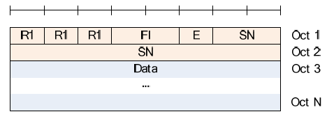
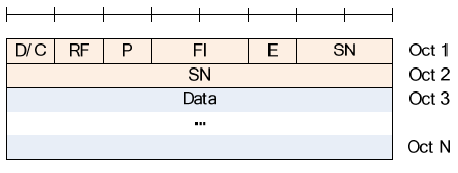
is a data structure for UMD (UM mode data) structure. What are the
meaning of Fl, E, SN ? You should refer to other sets of diagrams later.
If you remember the diagram in previous section (Fig 4.2.1.2.1-1), RLC
UM entity has capability of segmentation/concatenation. It means ... if
the incoming data is greater than the RLC size, it segment the data into
multiple chunks and pass
them one by one. In this case, you have to put some tag (number) to each
of the chunks.. otherwise the receiving side cannot combine them in
proper sequence. This tag (number) is SN (Sequence Number). As you see
in the following diagram, there are two different types of SN. One is 5
bits and the other one is 10 bits.

What
if the data coming into the RLC entity ? The simplest way is to pack
the small chunk as it is (as in TM mode), but it is waste of space.
Then
what do we have to do in this case ? The simplest way is to put the
multiple small chunk into a single RLC packet. In this case, you need
special information for each of the small chunk within the RLC packet.
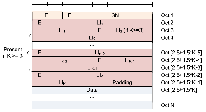
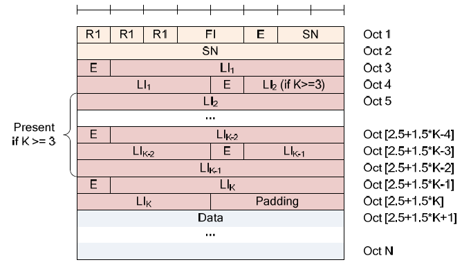
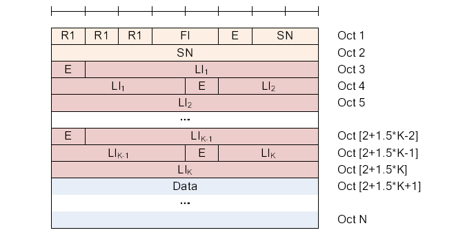
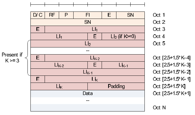
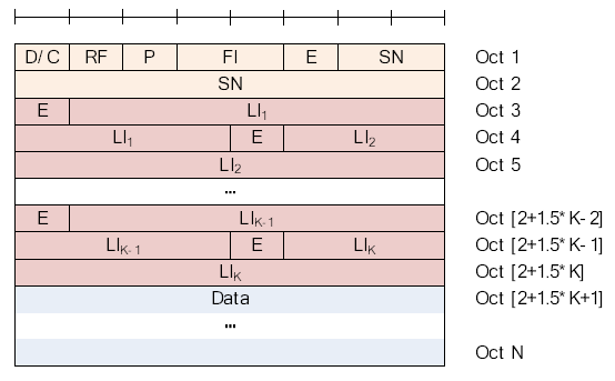
LI (Length Indicator) is the length value for each of the small chunks
within a RLC PDU.
The
last type of RLC packet type is AMD (AM mode data) structure. Overall
structure is very similar to UMD structure except that it has a couple
of additional field D/C, RF, P.
We saw many of small fields in RLC header and now let's try understanding the meaning of each of these fields.

FI Field :
This field indicate the relative location of the RLC PDU within a RLC
SDU. For example, '01' indicate the PDU is the first segment of the SDU
and '10' indicates the PDU is the last segment of the SDU, and '11'
indicate the PDU is in between the first and last segment. In a SDU,
there is only one '01'
type PDU and only one '10' type PDU. There can be one or more '11' type
PDU. If FI is 00, it means the RLC PDU is same as RLC SDU. When RLC
recieves '01' type, the layer start buffering the PDU within RLC memory
and only when it recieves '10' PDU, RLC reassembles all the recieved PDU
and transfer it to PDCP.


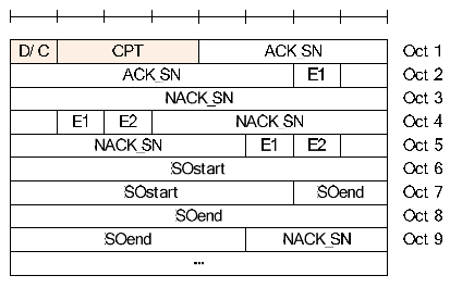
D/C Field : This field indicate whether the PDU is for RLC control or Data .

RF Field : This field indicate tye type of the AMD PDU.

P Field : This field indicate the PDU requires a status report (RLC ACK or NACK) from the other party or not.


No comments:
Post a Comment